The widespread use of LEDs begins in the mid 60-ies of the last century. Since then, this device has undergone many changes. And today, when LEDs have become much cheaper, their popularity among consumers has grown significantly. Lighting realized through the use of LEDs is ten steps ahead of incandescent lamps and fluorescent lighting devices - they are many times more economical, reliable and more durable.
What is an LED and how does it work
A light emitting diode is a device that uses the properties of a pn junction and emits photons, converts an electric current into light radiation, which occurs when the combination of electrons and holes is reversed in the pn junction region. That is, a necessary condition for connecting LEDs to obtain a glow is the pn junction, which is the contact of two semiconductors with different types of conductivity. For these purposes, semiconductor crystals are treated on the one hand with acceptor impurities, and on the other hand with donor impurities. Moreover, for light emission, the proximity of the energy of the visible light quanta with the band gap of the active region of the LED is necessary. In addition, an insignificantly small number of defects should be contained in the crystal, due to which the inverse combination of electrons and holes in the pn junction region occurs without radiation.
How to connect?
Connecting LEDs is subject to strict polarity. For these purposes, the leads of the LEDs have the corresponding names: anode and cathode. Accordingly - plus and minus.
The LED is capable of emitting a glow only when directly turned on. When turned back on, it irreparably fails.
Since the LED is capable of emitting light only at certain values of voltage and current strength, it is necessary to introduce a limiting resistance into the connection circuit.
How to connect the LED to 220 V?
How is this possible? Connecting an LED to a 220 V power source is not at all as easy as it might seem. The essence of the problem lies in the technical characteristics of the device, whose operation is based on the principle of passing current through the crystals, as a result of which they begin to produce a glow. To comply with this principle, another device is needed - a driver, whose job is to control the current supply to the crystal. In this case, the driver limits it to the amount necessary for specific models of LEDs used.
In another case, the LEDs are connected directly to a voltage of 220 V and is used when the LED should look like a low-power indicator and when only one or several elements are involved in the connection. In most cases, the LED is used as a light source and is connected via a driver, which already has all the necessary parameters for the normal operation of the device.
The LED will not produce a glow if the voltage applied to it is less than the required value. On the other hand, if such a voltage exceeds the desired value, the device will fail. To exclude such cases, a current-limiting resistor is used to connect the LED.
An approximate driver connection diagram for decorative LED illumination is presented below.
The main feature of the driver is the conversion of alternating current flowing in a conventional household outlet, and as a result, the LED is already supplied with direct current.
LED series connection
In the connection of such devices has its own characteristics. It is better to connect several LEDs at once in series. Such a connection will reduce energy consumption and allow you to connect a large number at the same time. But at the same time, all LEDs connected in series must be of the same type, and the power supply must have sufficient power and be able to provide the necessary voltage.
Connecting LEDs according to this principle is quite simple. Diodes are connected in series. A striking example of such a connection is the usual Christmas tree garland.
Arduino LED connection
How to solve the problem, so that the LED turns on and off at intervals of 1 second? The so-called sketch, a program created in the Arduino environment, can help us with this. Arduino is an electronic constructor and a convenient platform that has received the widest distribution among lovers of radio electronics, since this system is quite simple and convenient to use. Arduino-based devices can control various actuators. In particular, the LED.
The figure below shows the connection diagram of the LED to the Arduino controller, on which the device is connected to the eighth pin. This fact must be taken into account when programming, setting the necessary parameters.
Parallel connection
Parallel connection of LEDs is universally used by the population in everyday life - in any LED-display or LED-matrix.
LEDs have technological differences in the value of direct voltage reduction. Accordingly, various currents will pass through them. In this case, the light intensity will also vary, which the human eye perceives as different brightness. For this reason, currents must be aligned with ballast resistors.
The figure shows a diagram of the parallel connection of LEDs in one of the ways. Moreover, option “a” is erroneous; it is not recommended to be applied in practice. The correct option "b" - with ballast resistors.
Self connect
Do-it-yourself connection of LEDs must be done according to all the rules. For connection, it is necessary to use wires of small cross section due to the fact that the resistance of such a wire will be almost equal to the resistance of the LEDs. Moreover, experience shows that the voltage drops depending on the length of the wire. For this reason, power sources are located near devices operating on LEDs. Or they use power supplies for LEDs with an output voltage of 24 V, 36 V or 48 V. In turn, manufacturers of LED strips produce them for different voltages:
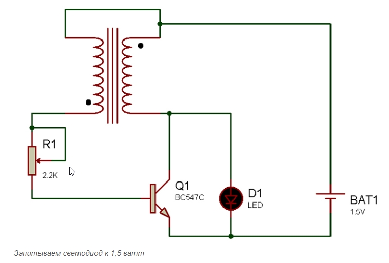
- Connection to 1.5 V. With this connection, LEDs, the operating voltage of which in most cases exceed 1.5 V, require a power supply of at least 3, 2 B. Moreover, a blocking generator with a resistor, a transistor and a transformer are used to connect .
- Connection to 5 B. This connection of the LED involves the connection of a resistor having a resistance in the range of 100-200 Ohms.
- Connection to 9 V. Such a power source is extremely rarely used to connect LEDs. Most often, three diodes with a working current of 20 mA are connected in series.
- Connection to 12 V. Includes determination of the type of unit, finding the rated current, voltage and power consumption. In the case of such a connection, it is necessary to use a resistor, which is located on any part of the electrical circuit.
- Connection to 220 B. With this connection, it is necessary to limit the level of current that will pass through the LED, and also to reduce the level of reverse LED voltage, since only in this way it will be possible to prevent a breakdown. Current level is limited by resistors, capacitors or inductors.
Let us dwell on connecting to a 220 V network.
The principle of connecting to high performance
How to connect the LED to the 220 V network? As already mentioned, a driver is needed for optimal assembly of the device, because in order to make such a connection and the devices can work stably, it is necessary to reduce the voltage amplitude and reduce the current strength, as well as convert the alternating voltage to constant. A divider that has a resistor or capacitive load, as well as various stabilizers, can help solve this problem.
Lamp switch
How to connect a switch with an LED? For us, the electric switch in apartments is no longer a wonder. However, progress does not stop, and manufacturers of lighting equipment have already improved our usual switches, providing them with LED backlight. Such devices provide for their highlighting when off. In the afternoon, such an improvement, of course, is imperceptible. But at night this seemingly trifle is unusually relevant. Connecting a switch with an LED is not a difficult task, as it is done in a very simple way. However, safety precautions require the observance of certain nuances.
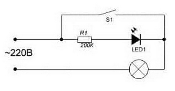
As can be seen from the presented diagram, the device consists of only two elements - a resistor that limits the current, and, in fact, a light source. The difficulty and a peculiar paradox are that the LED is placed in a 220 V AC switch. In this case, the LED itself is designed for a constant voltage of 2 to 12 V. However, when the current strength is significantly greater than this section of the connection circuit is capable of skipping, excess energy is converted into heat. And if there was no resistor in front of the LED, then the current passing through it, the diode crystal would simply evaporate. It's all about the resistor that cuts off most of the current.
Work algorithm
The LED connection in the switch is carried out in several stages:
- Turn off the power completely.
- We disassemble the switch, connect elements to its terminals in accordance with the above diagram.
- In the switch panel with a thin drill, we drill a hole for the LED output.
- We assemble the switch.
- We renew power supply.
- We use the device.