Metrology is the science of measurements, means and methods of ensuring their unity, as well as ways to achieve the necessary accuracy. Its subject is the allocation of quantitative information about the parameters of objects with a given reliability and accuracy. The regulatory framework for metrology is standards. In this article, we will consider the tolerance and landing system, which is a subsection of this science.
The concept of interchangeability of parts
In modern factories, tractors, automobiles, machine tools, and other machines are not manufactured in units or tens, but in hundreds or even thousands. With such volumes of production, it is very important that each part or assembly to be manufactured exactly fits its place during assembly without any additional fittings. After all, such operations are quite laborious, expensive and time consuming, which is not permissible in mass production. It is equally important that the parts arriving at the assembly allow replacement with other general purpose ones, without any damage to the functioning of the entire finished unit. This interchangeability of parts, assemblies and mechanisms is called unification. This is a very important moment in mechanical engineering, it allows you to save not only the costly part for the design and manufacture of parts, but also the production time, in addition, the repair of the product as a result of its operation is simplified. Interchangeability is the property of components and mechanisms to occupy their places in products without prior selection and to perform their basic functions in accordance with the technical conditions.
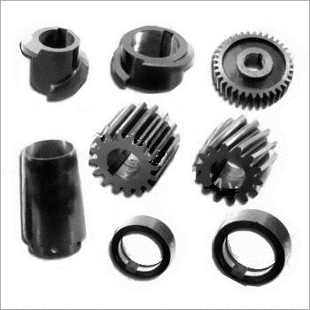
Mate parts
Two parts, motionlessly or movably connected to each other, are called mating. And the size by which this articulation is carried out is usually called the mating size. An example is the diameter of the hole in the pulley and the corresponding shaft diameter. The value by which the connection does not occur is usually called the free size. For example, the outer diameter of a pulley. To ensure interchangeability, the mating values of the parts must always be accurate. However, such processing is very complex and often impractical. Therefore, the technique uses a method for producing interchangeable parts when working with so-called approximate accuracy. It lies in the fact that for different operating conditions, the nodes and parts specify the permissible deviations of their sizes, in which the perfect functioning of these parts in the unit is possible. Such indents, calculated for various working conditions, are built in a given specific pattern, its name is "a single system of tolerances and landings."
The concept of tolerances. Characterization of quantities
The calculated data of the part supplied in the drawing, from which the deviation is counted, is usually called the nominal size. Usually this value is expressed in whole millimeters. The size of the part that is actually obtained during processing is called valid. The values between which this parameter fluctuates are commonly called limiting. Of these, the maximum parameter is the largest size limit, and the minimum is the smallest. Deviations are the difference between the nominal and the limiting value of the part. In the drawings, this parameter is usually denoted in numerical form at a nominal size (the upper value is indicated above, and the lower - below).
Record example
If the value 40 +0.15 -0.1 is indicated on the drawing, this means that the nominal size of the part is 40 mm, the largest limit is +0.15, and the smallest is –0.1. The difference between the nominal and maximum limit value is called the upper deviation, and between the minimum - the lower one. The actual values are easily determined from here. From this example it follows that the largest limit value will be 40 + 0.15 = 40.15 mm, and the smallest: 40-0.1 = 39.9 mm. The difference between the smallest and largest limit sizes is called tolerance. It is calculated as follows: 40.15-39.9 = 0.25 mm.
Clearances and interference
Consider a specific example where tolerances and landings are key. Suppose we need to fit a part with a hole of 40 +0.1 onto a shaft with dimensions of 40 -0.1 -0.2 . It can be seen from the condition that the diameter in all cases will be smaller than the hole, which means that with such a connection, a gap will necessarily occur. This landing is usually called mobile, because the shaft will rotate freely in the hole. If the size of the part is 40 +0.2 +0.15 , then under any condition it will be larger than the diameter of the hole. In this case, the shaft must be pressed in and an interference will occur in the joint.
conclusions
Based on the above examples, the following conclusions can be made:
- The gap is the difference between the actual dimensions of the shaft and the hole when the latter is larger than the first. With this connection, the parts have free rotation.
- An interference fit is the difference between the actual dimensions of the hole and the shaft when the latter is larger than the first. With this connection, the parts are pressed in.
Landing and accuracy classes
Landings are usually divided into motionless (hot, press, light-pressed, deaf, tight, dense, tense) and mobile (sliding, running, movements, light-running, wide-stroke). In machine and instrument engineering, there are certain rules that govern tolerances and landings. GOST provides certain accuracy classes in the manufacture of nodes using specified deviations in size. It is known from practice that the details of road and agricultural machines without harm to their functioning can be made with less accuracy than for lathes, measuring instruments, automobiles. In this regard, tolerances and landings in mechanical engineering have ten different accuracy classes. The most accurate of them are the first five: 1, 2, 2a, 3, 3a; the following two are of medium accuracy: 4 and 5; and the last three are gross: 7, 8, and 9.
In order to find out what accuracy class a part should be made, a figure indicating this parameter is put on the drawing next to the letter indicating landing. For example, the marking C4 means that the type is moving, class 4; X3 - running type, 3rd class. For all second-class landings, a digital designation is not set, since it is the most common. You can get detailed information about this parameter from the two-volume reference book “Tolerances and Landings” (V. Myagkov, 1982 edition).
Shaft system and bore
Tolerance and fit are considered as two systems: holes and shaft. The first of them is characterized by the fact that in it all types with the same degree of accuracy and class belong to the same nominal diameter. The holes have constant values of limit deviations. A variety of landings in such a system is obtained by changing the maximum deviation of the shaft.
The second of them is characterized by the fact that all types with the same degree of accuracy and class belong to the same nominal diameter. The shaft has constant values of limit deviations. A variety of landings is carried out as a result of changing the values of the maximum deviations of the holes. In the drawings, the hole system is usually denoted by letter A, and the shaft by letter B. A sign of accuracy class is placed near the letter.
Designation Examples
If “30A3” is indicated on the drawing, this means that the part in question must be machined with the hole system of the third accuracy class, if “30A” is indicated, it means according to the same system, but of the second class. If the tolerance and fit are made on the principle of a shaft, then the required type is indicated for the nominal size. For example, a part with the designation "30B3" corresponds to processing according to the shaft system of the third accuracy class.
In his book, M. A. Paley (“Tolerances and Landing”) explains that in mechanical engineering the principle of the hole is used more often than the shaft. This is due to the fact that it requires less equipment and tools. For example, in order to process a hole of a given nominal diameter according to this system, only one reamer is required for all landings of this class, and one limit plug is required to change the diameter. With a shaft system, a separate reamer and a separate plug are required to ensure each fit within the same class.
Tolerances and Landings: Deviation Table
To determine and select accuracy classes, it is customary to use special reference literature. So, tolerances and landings (a table with an example is given in this article) are, as a rule, very small quantities. In order not to write extra zeros, in the literature they are denoted in microns (thousandths of a millimeter). One micron corresponds to 0.001 mm. Typically, the first column of such a table indicates the nominal diameters, and the second indicates the deviation of the hole. The remaining columns give various values of landings with their corresponding deviations. A plus sign next to this value indicates that it should be added to the nominal size, a minus sign - that it must be subtracted.
Thread
The tolerance and fit of threaded connections should take into account the fact that the thread is mated only on the sides of the profile, the only exception is vapor-proof types. Therefore, the main parameter that determines the nature of the deviation values is the average diameter. The tolerance and fit for the outer and inner diameters are set so as to completely eliminate the likelihood of being crushed by the troughs and tops of the thread. Errors in reducing the external size and increasing the internal size will not affect the make-up process. However, deviations in the pitch of the thread and the angle of the profile will lead to jamming of the fastener.
Clearance Tolerances
The most common are clearance and fit with clearance. In such joints, the nominal average diameter is equal to the largest average nut thread. Deviations are usually counted from the profile line perpendicular to the axis of the thread. This is defined by GOST 16093-81. Tolerances for the thread diameter of nuts and bolts are assigned depending on a given degree of accuracy (indicated by a number). The following series of values for this parameter are accepted: d1 = 4, 6, 8; d2 = 4, 6, 7, 8; D1 = 4, 6, 7, 8; D2 = 4, 5, 6, 7. Tolerances for them are not established. The placement of the fields of the thread diameter relative to the nominal profile value helps to determine the main deviations: upper for the external values of the bolts and lower for the internal values of the nuts. These parameters directly depend on the accuracy and pitch of the connection.
Tolerances, fit and technical measurements
For the production and processing of parts and mechanisms with specified parameters, the turner has to use a variety of measuring tools. Typically, rulers, calipers and calipers are used for rough measurements and dimensional verification of products. For more accurate measurements - calipers, micrometers, calibers, etc. What a ruler is, everyone knows, so we will not dwell on it.
The caliper is a simple tool for measuring the external values of workpieces. It consists of a pair of rotary curved legs fixed on one axis. There is still a spring-type caliper, it is set to the required size with a screw and nut. Such a tool is a little more convenient than a simple one, because it saves the set value.
Nutromer designed to take internal measurements. It happens ordinary and spring type. The device of this tool is similar to a caliper. The accuracy of the instruments is 0.25 mm.
A caliper is a more accurate fixture. They can measure both the external and internal surfaces of the workpieces. When working on a lathe, a turner uses a caliper to take measurements of the depth of the undercut or ledges. This measuring tool consists of a bar with divisions and jaws and a frame with a second pair of jaws. Using the screw, the frame is fixed on the rod in the required position. The measurement accuracy is 0.02 mm.
Caliper - this device is designed to measure the depth of grooves and grooves. In addition, the tool allows you to determine the correct position of the ledges along the length of the shaft. The device of this device is similar to a caliper.
Micrometers are used to accurately determine the diameter, thickness and length of the workpiece. They give readings with an accuracy of 0.01 mm. The measured object is located between the micrometer screw and the fixed heel, adjustment is carried out by rotating the drum.
Nutrometers serve for accurate measurements of internal surfaces. There are permanent and sliding appliances. These tools are rods with measuring spherical ends. The distance between them corresponds to the diameter of the hole being determined. The measurement range for the caliper is 54-63 mm, in the presence of an additional head, diameters up to 1500 mm can be determined.