Oil refineries and technological complexes using oil and gas products contain a pipeline system in the working infrastructure for servicing fuel materials. Maintaining sufficient performance in the circuits of the same oil requires the use of special plumbing fixtures. Its key element is the tank breathing valve, due to which pressure is regulated under conditions of depressurization and vacuum of the operated tank.
Device purpose
The range of applications for such valves is extensive and covers almost all the niches where oil and gas products storage processes are organized. The use of special control valves for tanks containing fuel is determined by the requirements for the safe operation of such facilities. Petroleum products are combustible, fire and explosive raw materials, which leads to high requirements for its content. And this is not to mention the special rules for the long-term storage of oil, in which its optimal working properties are preserved.
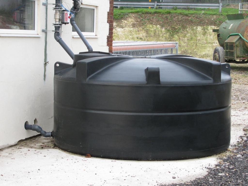
How can the reservoir breathing valve help in this context? The purpose of such devices in a broad sense can be reduced to ensuring the sealing of the capacitive space where the target storage products are contained. As a rule, we are talking about tanks with a gaseous medium, which must be protected from the penetration of flame. The function of regulating internal pressure is also basic and determining the degree of safety when servicing oil storage facilities.
Structural design
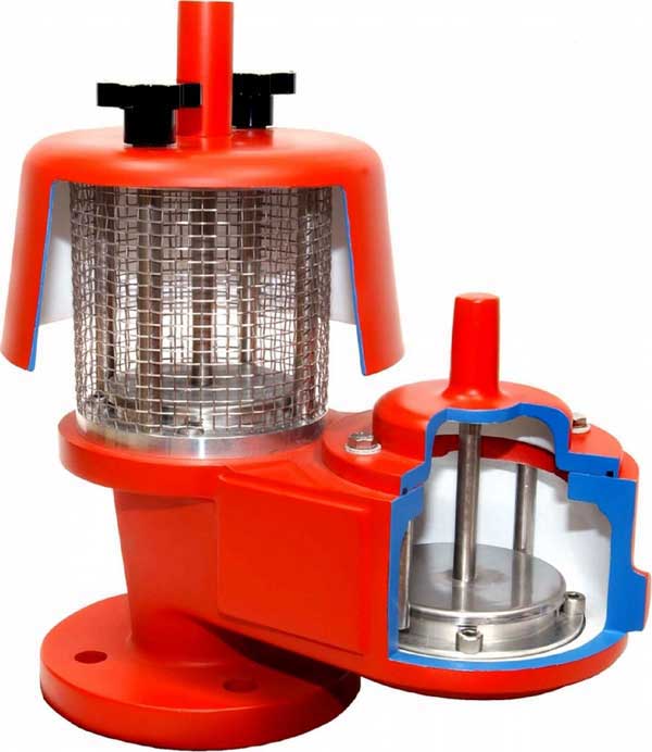
The most common group of control valves in this class is the breathing valve of the SMDK reservoir, that is, a combined mechanical regulator, in the device of which a standard pressure plate and a pressure plate with loads are provided. On the back side, the housing is provided with a refractory screen, which prevents the passage of flame into the tank with fuel products. This option is enabled at the moments when gas mixtures and vapors leave the tank together with air. Plates of vacuum and pressure can change their position by adjusting the volume of the buffer zone.
The working mechanical organs of the structure include a handling device (removal and installation), clamp brackets, a flywheel, flange fasteners, etc. However, the type of form factor often depends on the choice of design, on which the direction of the gas flow. For example, the device of the tank breathing valve is designed to orient the flow downward vertically, which makes it difficult to remove heat while stabilizing combustion. Accordingly, the fire resistance of the fuse itself is reduced. This configuration is typical for non-freezing controllers, in which the valve surfaces are horizontal. But one should not fully rely on the frost resistance of such reinforcement elements - in particular, it is on the external surfaces that the frozen condensate can have a thickness of up to 50 mm, which cannot but affect the performance of the fuse as a whole.
Principle of operation of reservoir breathing valves
The simplest operation schemes of industrial breathing valves can be compared with the function of air vents, which are widely used to remove excess air from domestic pipelines. In this case, the same principle of formation of a buffer zone with two levels of regulation of the passage of excess steam and air applies. In the normal state, both valves are closed, and the change in throughput starts from the moment the pressure indicator in the circuit is exceeded, which, naturally, causes the shutter to rise from the seat. A specific indicator of pressure at which the tank breathing valve starts the release of excess gas-air mixtures is set individually in accordance with the requirements for the serviced area. Moreover, the conditional point of activation of the valves can be not only a high pressure value, but also sharp temperature fluctuations, as well as excessive under-pressure with the formation of a vacuum. In conclusion of the above, it can be summarized that when the overpressure is fixed, the pressure control valve enters into operation, and in case of excessive depression, the system of vacuum valves. The regulation process itself involves either the release of excess steam and air, or increased sealing in the conditions of artificial injection of technical gas mixtures.
Mechanical shut-off valves
The oldest and most common breathing valve release format, designed to maintain a sufficient level of pressure in horizontal containers with oil and gas materials. But this group has its own differences. So, closed-type models are used to trap vapors of easily evaporating products, and the combined mechanical breathing valve is used for gas station tanks (gas stations), where the preservation of the operational properties of the resource is required. What is the difference between a design with a mechanical shutter in principle? Mainly - ways of mounting plates on the case. For example, fixation may be provided by rigid guide rods or peripheral plate suspensions using clamps. The difference between the two different approaches to installing the shutter is the same as when attaching conventional piping lines. Rigid fastening ensures the stability of the mounting connection and the immobility of the circuit, which is beneficial when operating communications of small capacities. However, even slight vibrations during the maintenance of a large tank can deform or completely disrupt the installation site of the rigid fixture. Therefore, in such systems it is customary to use "floating" mechanical fixation with clamps that provide a small range for vibrations.
Hydraulic shutoff valves
Hydraulic locks operate on the principle of regulating the internal pressure created by a low-viscosity, slightly evaporating and non-freezing liquid, which is poured into the design of the regulator. This may be a solution of glycerin, hydrochloric oil, diesel, ethylene glycol and other mixtures that are capable of forming sufficient force for the hydraulic shutter to work. The valve itself is mounted strictly horizontally, since its work is calculated on creating a reduced vacuum and regulating the pressure as a result of lowering the mass of the liquid relative to the standard value. The hydraulic valves of the breathing valve for the tank are replaced by mechanical closures in order to more effectively regulate the pressure in storages with products characterized by high volatility. In hydraulic valves there is a membrane that separates the vapor-gas space of the tank from the atmosphere, if necessary, also extinguishing the flame inside the circuit due to the built-in fire fuse.
Valve design
The main design data that are used in the design process of industrial breathing valves include indicators of throughput. This data directly depends on the circuit performance and flow control capabilities. Moreover, in the calculations of breathing valves for tanks, two indicators of throughput are used - according to internal pressure, and according to vacuum. In both cases, the output is presented as a specific indicator of the volume of fluid passage for 1 hour. For direct calculation, the performance parameter of the bay and the discharge of the product from the tank is used. It affects the amount of bandwidth and the characteristics of the served environment. Depending on the properties of the same oil product, the coefficient of productivity accounting may change. For example, the rate of contamination of crude oil has a significant effect.
Valve accessories
After determining the parameters of the valve and the characteristics of its design, you can proceed to the selection of elements through which the device will interact with the communications of the tank. First of all, this refers to the pipe connection to the tank. Two parameters will be important - the nozzle diameter and productivity. Actual throughput will be limited by the valve itself, and the diameter of the connection pipe will determine the flow rate, which is not regulated by technical documentation. Nevertheless, there are general regulatory requirements for the breathing valves of tanks, which note that, in principle, the use of connection nodes with a thickness of less than 350 mm should not be. There is also an upper limit of 1500-1700 mm, at which a high center of gravity and a large windage are noted, which ultimately gives significant loads on the pipe. When choosing a communication link for a valve-pipe, it is optimal to adhere to a format of 400-600 mm, taking into account also external influences during operation.
If necessary, the regulation unit is supplied with stretch marks. They are usually recommended for use as an auxiliary element at valve installation sites, where the greatest hydraulic load is expected. Stretch marks are fixed on the roof of the tank, which provides additional insurance for the working infrastructure.
Another important component of control valves is the disk reflector. It is used to reduce the loss of oil and gas mixtures during the evaporation process. The reflector disk works in combination with the reservoir breathing valve, reducing emissions of marketable raw materials by 3-5%. This device forms a kind of filter umbrella over the ejection channel, diverting part of the flows of the useful product into a horizontal plane. At the next stages of technological processing, these mixtures are received by special collectors and transported to the main channel for the circulation of the oil and gas product without deterioration in performance.
Valve application
Immediately prior to installation, the valve bracket with covers must be lifted up, and then plates and transport sleeves should be removed. Next, the housing structure must be purged with compressed air and reassemble in the reverse order. The valve is installed on the tank communications through a special flange of a suitable format. The joint also uses a gasket for sealing. Mechanical fastening is carried out by bolts and nuts, suitable in design to a specific unit of the installation. Subsequently, during operation, periodic maintenance of the respiratory valve of the tank is carried out, which may include repair measures. For example, as a result of a technical inspection or during normal operation of the circuit, the following problems are often identified:
- Uncharacteristic change in pressure indicators. It is usually associated with contamination of the fuse cartridge. Rinse this device with kerosene and then purge it with air.
- Depressurization at the junction of the tank nozzle with the breathing and safety valve. It is recommended that you check the photoplastic coating or rubber gasket. Sometimes such problems arise due to icing of the valve neck.
- Depressurization at the mounting location of the shutter. With a greater degree of probability there are violations in the design of the clamp fastening. It is not necessary that the clamp itself be damaged - it is possible that during its adjustment the range of free positions of the clamp was incorrectly adjusted.
Tank Respiratory Valve Check
Far from always the above-mentioned problems are identified in the process of general maintenance of tanks with oil products, and even more so are noticed in normal operation. At the same time, the slightest deviation in the performance of the pressure regulator can lead to a fire at the serviced station, not to mention other negative factors associated with the uncontrolled release of flammable vapors and liquids. Accordingly, in a separate order, a special check of the tank breathing valves must be performed, during which the current state of the pipeline, the roof of the tank and the working medium is analyzed. In the framework of events of this kind:
- Checking valve capacity under pressure conditions to the level of optimal performance.
- Checking the capacity of the regulator under vacuum conditions.
- Checking the mechanics of the action of valves at the moments of closing and opening plates with gates.
- If necessary, commissioning with the regulation of the operating parameters of the valve.
At each object of application of this armature, its own schedule for carrying out diagnostic operations is established. On average, the frequency of checking the respiratory valves of reservoirs is 1-2 times per month. Typically, in the summer, such events are performed more often than in the winter. At the same time, the reservoir during operation must be subjected to a general inspection on a daily basis. Based on the results of all examinations, a protocol is drawn up with data recorded during the audit.
Conclusion
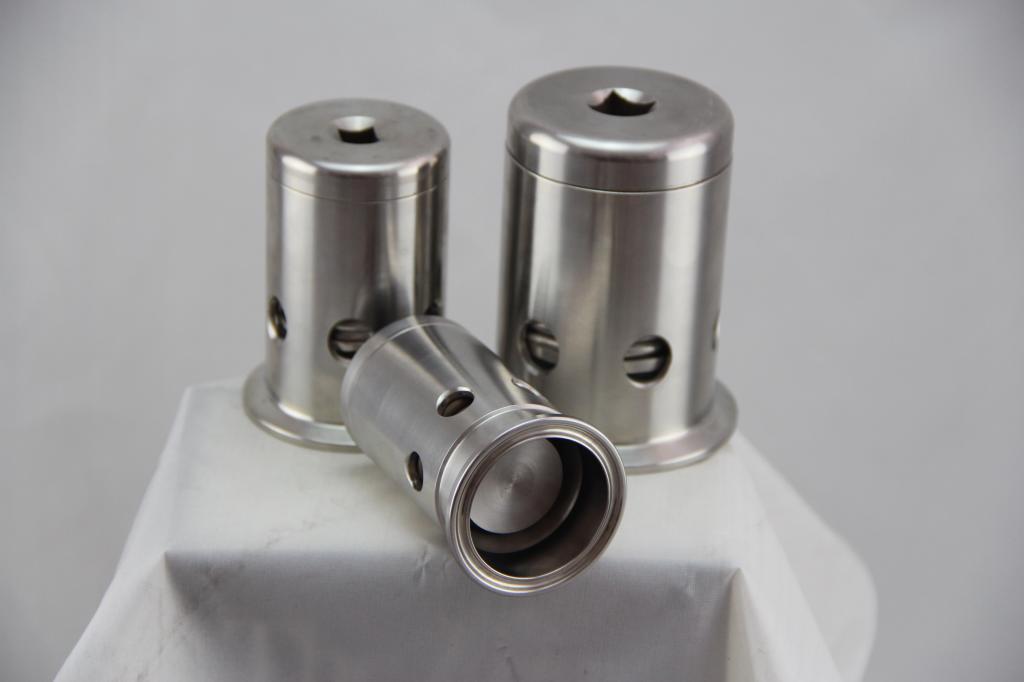
The concept of using auxiliary valves with valves and other structural means of regulation is gradually becoming a thing of the past. Manufacturers of pipeline systems are trying to shift regulatory and safety functions to integrated oil storage management stations. However, the complete withdrawal of the respiratory valves from the practice of speech is not yet discussed. Moreover, there are promising areas of their technological development. In particular, the widespread format of the breathing valve for the gas station reservoir in recent years has acquired a removable flame arrester and received a die-welded body. The first innovation made it possible to use the device in regions with extremely low temperatures in winter, and the second one reduced the construction weight by 2 times. The fourth generation valves also reduced the number of movable elements, which increased their operational reliability.
Some manufacturers also pay attention to optimizing valve maintenance processes. So, a very convenient solution, from the point of view of operation, was the introduction of fixed casings with a special placement configuration, which does not require the dismantling of entire groups of parts for internal inspection of the valve structure.