The alignment of the shafts of electric motors and mechanisms is carried out with the aim that their axes are on one straight line. Misaligned rotating shafts create significant loads, leading to destruction, premature failure of parts and significant noise.
It is not always possible to coaxially set the mechanisms; therefore, couplings are used with compensation of the axle alignment by elastic elements. They perform their functions to a certain amount of misalignment. The alignment of the shafts on the coupling halves is most convenient. Their surfaces are basic, and measuring devices are attached to them. In the power system, most of the machines work with elastic sleeve-finger couplings (MUVP). In powerful units gear couplings (MZ) are used.
Centering Options
The alignment of the shafts with indicators is checked according to the following parameters:
- R is the mutual radial displacement of the cylindrical surfaces of the coupling halves (radial descent).
- T is the difference in the disclosure of the ends of the coupling halves in the vertical and horizontal planes (end or angular misalignment).
Coupling Requirements
Permissible misalignment decreases with increasing speed. It is 0.12 mm at 1500 rpm for the MUWP and 0.05 mm at 3000 rpm.
Important! When choosing a coupling, it is necessary to check the conformity of its characteristics to technical conditions, according to which its axial and radial runout should not be higher than 0.05 - 0.08 mm. Landing on the shaft is tight. Before disassembling, labels are applied to the coupling halves, according to which they can be restored to their relative position. Violation of these rules may reduce alignment accuracy.
Horizontal shaft mounting
In fact, the axis is not straight, as it bends under the influence of its own weight and other loads. When aligning the unit, you need to control the position of the shafts relative to the horizon. Control is carried out on the necks of bearings. You can use the adjacent even shaft surface nearby using the “Exploration” level (division price 0.1 mm per 1 m).
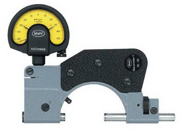
Centering Devices
Experienced craftsmen are able to control alignment by applying a metal ruler to the clutch and determining alignment in clearance. But for greater certainty, in order to meet the norm, you can use the plate probe or the ICh-0.01 indicator. The latter provides the necessary accuracy of 0.01 mm, which is enough to meet the norm.
First, the coupling halves are disconnected, and then devices for centering the shafts of electric machines are installed on them or on the shafts nearby. They must be rigid enough so that they do not bend during the measurement process. Measurements can also be made with coupled couplings.
After installing and strengthening the fixtures, the operability of the indicator mechanism is checked. To do this, the measuring rods should be pulled back and replaced. In this case, the arrow should come to its original position.
Axial and radial clearances are checked by simultaneously turning both rotors from the starting position at angles of 90 °, 180 ° and 270 ° in the direction of rotation of the drive.
How to center the units?
Before measurements, the tightness of the anchors and bearing housings is checked . Weakening of the fastening, the presence of cracks in the frame, defects in the foundation, uneven settlement of the floor are causes of misalignment during the operation of the mechanisms.
Devices are installed on the coupling halves, then the alignment is measured:
- radial in the vertical plane;
- radial in the horizontal plane;
- end in a vertical plane;
- end in the horizontal plane.
According to the measurement results, the position of the shaft axes is adjusted. To do this, the supports are moved vertically using gaskets, and horizontally with bolts located on the frame. The alignment bracket is set to a position of a larger value of the alignment parameter, after which the supports are moved by the value of the actual alignment.
The alignment of the shafts is made alternately in horizontal and vertical planes. After the end of the process of moving and fixing the supports, the measurements are repeated. If necessary, they are corrected again.
Alignment of pumping units
The alignment of the pump and motor shafts is necessary to balance the rotating parts. This applies not only to the wheel and shaft, but also to the rotor of the electric motor. It is the responsibility of the manufacturer to demonstrate the unit in the operating feed mode without exceeding the permissible vibration level. Prices for industrial units are high, and with further operation it will be almost impossible to prove the manufacturer’s guilt.
The standards stipulate that after start-up the responsibility for vibration rests with the consumer. Tests of the pump should be carried out at the regular place of its operation. Particular attention is paid to the foundation and support frame on which the engine and pump are installed.
Joining places (mounting flanges) should be carefully processed so that the gap dimensions are not more than 0.2 mm per 1 m of joint. At the joints, it is possible to adjust the levels with gaskets with a thickness of 1.5 to 3 mm.
For pumps with power above 150 kW, according to the standard, centering is done with screws in the vertical and horizontal planes (at least six screws for a horizontal pump and at least four for a vertical). Their number depends on the weight of the equipment.
Important! The alignment of the connection between the drive and the pump is made and monitored before installation and during the entire period of operation. You also need to pay attention that the engine and the domestic pump are placed in a common housing and centered at the factory. They do not need to be controlled and exposed.
If a gearbox is installed between the pump and the motor, you should first center it and secure it with pins. The remaining shafts of the unit are guided by it. Upon receipt of the pumps from the factory assembled with electric motors, the alignment of the shafts of the units is carried out by the engines. When assembling the pump on the support frame, the motor shaft is set on it.
Propeller shaft balancing
The propeller shaft is centered to eliminate vibrations that occur when the engine is running. The reasons for the imbalance may be:
- violation of the requirements for shaft manufacturing technology or after its repair;
- incorrect assembly;
- misalignment of shaft parts and mating parts of the transmission;
- errors of heat treatment of the product;
- mechanical damage.
First, an imbalance is detected, and then it is eliminated by installing a counterweight. Work is performed on special equipment of a service station. To do this, use balancing machines.
Actual operating conditions of the driveshaft are simulated due to its rotation by an electric motor through a transmission (usually a belt drive).
Deviations are determined by sensors moving along the shaft. A special program processes the measurement results, after which the installation location and the value of the balancing weight are determined. A service technician adds weight, drills metal, or install gaskets to ensure alignment.
Centering devices
The simplest measurements can be made when checking the alignment of the shafts using a folding meter and a metal ruler. For correct measurements, a more accurate device for aligning the shafts is necessary: a bracket with a reading device, a plate probe, a micrometer, a caliper.
- Caliper - a device for measuring diameters (external and internal) and length of parts up to 4000 mm. Separate types allow you to determine the depth, distance to the inner and outer ledges, to make markings. The accuracy level is from 0.01 mm to 0.1 mm. Devices can be mechanical and digital - with the conclusion of the measured values on the display. Measurements are made with the weakening of the rod mounting, after which the measuring outer sponge is moved until the shaft is slightly clamped on both sides. Then the micrometer feed screw brings the frame with a nonius and is fixed with a clamp. Whole millimeters are counted by divisions on the bar, and fractions - by the nonius.
- Micrometer - a device for measuring the outer diameters and lengths of parts up to 2000 mm with an accuracy of ± 0.001 mm to 0.01 mm. During measurements, the part is clamped by the measuring surfaces of the device by rotating the micrometer screw with a ratchet, until the latter begins to slip.
- Staples with a reading device are used to measure external diameters and lengths of parts up to 1000 mm. The device for aligning the shafts is mounted on the rear heel, and the indicator with divisions is located on the movable heel. Measurements can be made with an accuracy of ± 0.002 to 0.01 mm.
- Plate probe - a set of calibrated plates for measuring the gaps between the ends of the coupling halves of the centered shafts. It can be used as an indicator of the gap between the centering bracket pin and the coupling half housing. The feeler plates are inserted into the gap with little friction, which is maintained approximately the same for each measurement.
- Level - a device for checking the horizontal position of foundation plates and unit frames with drives, as well as for aligning the lines of electric drive shafts and mechanisms. A frame device of the Geological Exploration type is used, where the angle of inclination is determined by the movement of the micrometer screw until the air bubble in the ampoule with the liquid reaches the zero position.
Laser shaft alignment
Laser alignment systems are available in single and double beam. The latter is more accurate and functional.
The measuring unit is mounted on the shaft and creates a laser beam along its center of rotation. From the opposite unit mounted on the mating shaft, another beam is detected. Both signals are captured by photodetectors, and at different angular positions of the shafts, their alignment is determined with high accuracy. By comparing the readings for different angular movements of the shafts, they can be centered in the horizontal and vertical planes.
System "Quantum-LM"
Shaft alignment using the Quant-LM laser system developed by BALTECH is very popular. Alignment of horizontal and vertical machines is performed. An integrated computing unit compares and processes the signals from the measuring units. The results are displayed on the display, which shows the alignment status with respect to the allowable area highlighted in green and the beyond zone (red).
The Kvant-LM system allows eliminating vibrations, reducing the number of downtimes and repair work, and increasing the service life of bearings, seals and couplings.
Conclusion
The alignment of the rotors of the units is a common defect that can be eliminated. To do this, you need to know the factors influencing it and the alignment of the shafts. Typically, the alignment of the shafts is made concentric and parallel installation of the end surfaces of the coupling halves using special devices.