The design of this unit is described in textbooks of 8th grade in physics. About the device of a steam turbine is described in books as follows. This type of turbine is a type of engine in which steam or heated air is able to rotate the engine shaft without interacting with a piston, connecting rod or crankshaft.
Brief description of the device
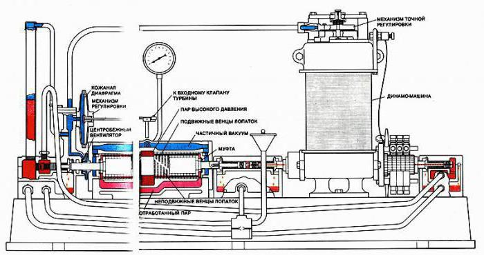
Briefly, the arrangement of a steam turbine can be described as follows. A disk is attached to the main element, that is, the shaft, to which the blades are attached. Parts such as nozzle tubes are also located near these elements. Through them, steam is supplied from the boiler. When steam passes through the nozzle, it exerts a certain pressure on the blades, as well as the disk of the entire installation. It is this effect that drives the turbine disk along with the blades.
Currently, in such units, most often several discs are used, which are mounted on one shaft. With this arrangement of a steam turbine, the following occurs. The energy of the steam passing through each blade of each disk will give part of its energy to these elements. The main application of steam turbines found in nuclear as well as thermal power plants, where they are connected to an electric current shaft. The rotation speed of the steam turbine shaft reaches 3000 rpm. This value is sufficient for the acceptable operation of electric current generators.
If we talk about the use of these units, it is worth mentioning that they are successfully operated on ships and vessels. However, due to the arrangement of the steam turbine, in particular, due to the fact that a large amount of water is required for the turbine to operate, its operation on land and air vehicles is impossible.
Turbine nozzle device. What does it affect
One of the most important elements for the operation of the device was the nozzle, through which the passage of steam is carried out.
In the earliest design of a steam turbine, when things such as steam expansion had not yet been fully studied, it was problematic to build a rationally functioning unit with high efficiency. The reason was that the nozzle that was used initially had the same diameter over its entire length. And this entailed the fact that the steam, passing through the pipe and falling into the space with less pressure than inside, lost pressure and increased its speed, but only to a certain value. If we talk about the saturation of dry steam, then its pressure at the outlet of the tube cannot be less than 0.58 of the initial pressure. This parameter is called critical pressure. Based on this value, it is possible to obtain the maximum velocity of the vapor, which is also called the critical velocity, and its value for superheated steam is 0.546 of the initial pressure.
These parameters were not enough for the normal functioning of the turbine. In addition, when exiting a nozzle of this shape, the steam began to swirl due to expansion in the atmosphere. All these shortcomings were eliminated when the device of the steam turbine, its nozzle, was changed. At the beginning of the selection, the pipe was narrow, gradually expanding towards the end. The main distinguishing feature, which has become a decisive factor, is that with this form it has become possible to bring the pressure at the end of the nozzle to the ambient pressure after the pipe. This solved the problem with steam clubs, which greatly reduced the speed, and also managed to achieve supercritical values for this parameter, as well as pressure.
Steam turbine design and principle of operation
It is important to say here that a steam turbine uses two different operating principles, which depend on its design.
The first principle is called active turbines. In this case, we mean devices in which steam expansion is carried out only in stationary nozzles, and also before it enters the working blades.
The device of a steam turbine and the principle of operation of the second type are called reactive. These units include those in which the expansion of steam occurs not only before it enters the working blades, but also during passage between them. Still such devices are called reaction-driven. If the heat drop in the nozzles is about half of the total heat loss, then the turbine is also called reactive.
If we consider the device of a steam turbine and its main elements, then you need to pay attention to the following. Inside the turbine, the following process takes place: a stream of liquid that is directed to the blade will exert pressure on it, which will depend on parameters such as flow rate, speed at the entrance, as well as at the exit to the surface, the surface shape of the blade, and the angle of the jet in relation to to this surface. It is important to note here that with such work it is not at all necessary to make the water flow hit the blade. On the contrary, it is customary to avoid this in the devices of steam units, and most often they make the jet smoothly flow around the blade.
Active work
What is the structure of a steam turbine operating on this principle. Here, the law is taken as the basis that any body possessing even a low speed can have high kinetic energy if it moves with high speed. However, here it must immediately be taken into account that this energy disappears very quickly if the speed of the body begins to fall. In this case, there are two options for the development of events if the steam jet hits a flat surface that is perpendicular to its movement.
The first option - the blow occurs on a fixed surface. In this case, all the kinetic energy possessed by the body will partially turn into thermal energy, and the rest will be spent on dropping the liquid particles in the opposite direction, as well as back. Naturally, no useful work will be done.
The second option is that the surface can move. In this case, some of the energy will be spent on moving the platform, and the rest will still be wasted.
In the arrangement of the steam turbine and the principle of operation, which is called active, it is the second option that is used. Naturally, you need to understand that when operating the unit, it is necessary to ensure that the energy consumption for useless work is minimal. Another important condition is that it is necessary to direct the steam jet so that it does not damage the shoulder blades upon impact. To achieve this condition is possible only with a certain surface shape.
Through testing and calculations, it was found that the best surface for working with steam jets is one that can provide a smooth rotation, after which the movement of the working substance will be redirected in the opposite direction from the original. In other words, it is necessary to give the shoulder blades the shape of a semicircle. In this case, when faced with an obstacle, the maximum part of the kinetic energy will be transmitted to the mechanical device, causing it to rotate. Losses will be minimized.
How an active turbine works
The device and principle of operation of a steam turbine of the active type is as follows.
Fresh steam with certain values of pressure and speed is transferred to the nozzle, where it expands also to a certain pressure indicator. Naturally, along with this parameter, the jet velocity will also increase. With an increased speed value, the steam flow reaches the mechanical parts - the blades. Acting on these elements, the jet of the working substance makes the disk rotate, as well as the shaft on which it is mounted.
Further, when leaving the blades, the steam flow already has a different velocity value, which will necessarily be lower than before these elements. This is due to the fact that part of the kinetic energy is converted into mechanical energy. It is also important to note here that while passing through the blades, the pressure value changes. However, it is important that at the input and output of these elements, this parameter has the same value. This is due to the fact that the channels between the blades have the same cross section along their entire length, and additional vapor expansion does not occur inside these parts. In order to let off steam that has already worked out, there is a special pipe.
Turbine mechanical device
The design and operation of a steam turbine from the point of view of mechanics look like this.
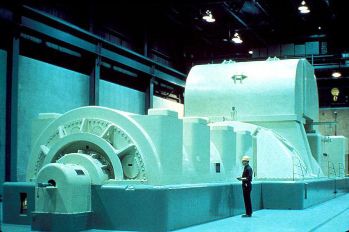
The unit consists of three cylinders, each of which is a stator having a fixed body, as well as a rotating rotor. Separately located rotors are connected by couplings. The chain, which is assembled from individual cylinder rotors, as well as from a generator and a pathogen, is called a shaft drive. The length of this device with the maximum value of the constituent components (currently it is not more than 5 generators) is 80 meters.
Further, the design and operation of the steam turbine look like this. The shaft drive rotates in elements such as thrust bearings in the liners. Rotation occurs on a thin oil film, while the metal part of these liners does not touch the shaft during rotation. To date, all rotors are placed on two bearings.
In some cases, between the rotors belonging to the CVP and the DSP, there is only one common support bearing. All the steam that expands in the turbine causes each of the rotors to rotate. All the power that is generated by each of the rotors is added to the total value on the coupling half and there reaches its maximum value.
In addition, each element is under the influence of axial force. These forces are combined, and their maximum value, that is, the total axial load, is transmitted from the ridge to the thrust segments. These parts are installed in the thrust bearing housing.
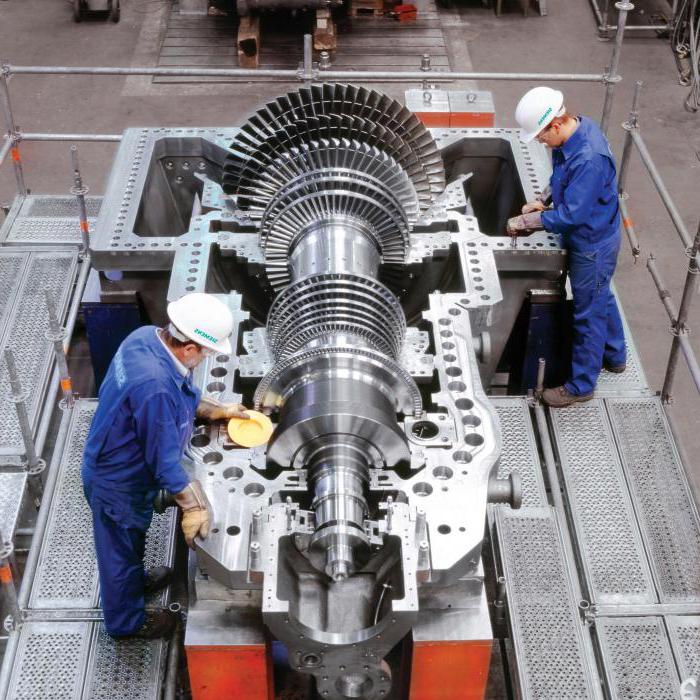
Turbine rotor device
Each rotor is placed in the cylinder body. Pressure indicators today they can reach 300 MPa, so that the housing of these devices is double-walled. This helps to reduce the pressure difference on each of them, which allows to reduce the thickness of each of them. In addition, this helps to simplify the process of tightening flange connections, and also allows the turbine to quickly change its power indicator if necessary.
Mandatory is the presence of a horizontal connector, which is designed for easy installation inside the case, and should also provide quick access to an already installed rotor during an audit or repair. When direct mounting of the turbine is carried out , then all the planes of the connectors of the lower bodies are mounted in a special way. To simplify this operation, it is generally accepted that all horizontal planes are connected into one common plane.
When in the future the moment of installation of the shaft-turning device of the steam turbine comes, it is placed in the existing horizontal connector, which ensures its alignment. This is necessary in order to avoid the impact of the rotor on the stator during rotation. Such a defect can lead to a rather serious accident at the facility. Due to the fact that the steam inside the turbine is characterized by a very high temperature, and the rotor rotates on oil films, the oil temperature should be no more than 100 degrees Celsius. This value is suitable both for fire safety requirements and corresponds to the presence of certain lubricating properties of the material. In order to achieve such indicators, the bearing shells are moved out of the cylinder body. They are placed at special points - supports.
Steam plants at nuclear power plants
The arrangement of a steam turbine at nuclear power plants can be considered with the example of saturated steam installations, which are available only at those facilities where water coolant is used. It is worth noting here that the initial characteristics of steam turbines at nuclear power plants are characterized by low rates. This forces the passage of a larger amount of working substance in order to achieve the desired result. In addition, because of this, increased humidity forms, which quickly increases along the steps of the turbine. This led to the fact that at such facilities it is necessary to use internal turbine and external moisture trapping devices.
Due to the high humidity of the steam used, the efficiency is reduced, and erosive wear of the flow parts quickly develops. In order to avoid this problem, it is necessary to use various methods of surface strengthening. Such methods include chrome plating, hardening, electric spark treatment, etc. If at other facilities it is possible to use the simplest device of steam turbines, then at a nuclear power plant one needs not only to think about corrosion protection, but also to remove moisture.
The most effective way to remove excess moisture from the turbine was the selection of steam. The selection of substances is carried out on regenerative heaters. It is important to note here that if such withdrawals are installed after each expansion stage, then the need for the development of additional intra-turbine dehumidifiers disappears. You can also add that the permissible limits of steam humidity are based on the diameter of the blade, as well as on the speed of rotation.
What is the arrangement of steam and gas turbines
The best quality, which has become the most important advantage of a steam turbine, is that it does not require any connection to the shaft of an electric generator. Also, this device coped well with overloads, and it could easily be adjusted in terms of speed. The efficiency of such units is also quite high, which, in combination with other advantages, brought them to the forefront if it became necessary to connect to electric generators. The same is the arrangement of the AEG steam turbine.
Similar objects were gas turbines. If we consider these devices from the point of view of design, then they are practically no different. Like a steam turbine, a gas turbine is a blade type machine. In addition, in both units, the rotation of the rotor is achieved due to the fact that the kinetic energy of the flow of the working substance is transformed.
A significant difference between these installations lies precisely in the type of working substance. Naturally, in a steam turbine, such a substance is water vapor, and in a gas installation it is gas that is most often obtained by burning any products, or is a mixture of steam and air. Another difference is that for the formation of these working substances it is necessary to have different additional equipment. Thus, it turns out that the turbines themselves are very similar, but the installations formed at the objects around them are quite different.
Condensed Steam Turbine
Losev S. M. described condensing devices and steam turbines in his book, published in 1964. The publication contained the theory, design and operation of steam installations, as well as condensing units.
The turbine unit, which is located in the boiler, has three environments - water, steam and condensate. These three substances form a closed cycle between themselves. It is important to note that in such an environment, during the conversion, a rather small amount of vapor and liquid is lost. To compensate for small losses, raw water is added to the installation, which before that passes a water treatment device. In this unit, the liquid is exposed to various chemicals, the main purpose of which is to remove unnecessary impurities from the water.
The principle of operation in such installations is as follows:
- Steam that has already worked out and has a reduced pressure and temperature enters the condenser from the turbine.
- During the passage of this section of the track, there are a large number of tubes through which cooling water is continuously pumped by means of a pump. Most often, this fluid is taken from rivers, lakes or ponds.
- At the moment of contact with the cold surface of the tube, the exhaust steam begins to form condensate, since its temperature is still higher than in the pipes.
- All accumulated condensate constantly flows into the condenser, from where it is continuously pumped out by the pump. After that, the liquid is transferred to the deaerator.
- , , .
, , .