A properly organized wiring system is an important technological characteristic of working conditions in various sectors of the national economy and industry from small welding production to energy enterprises. Not only the stability of the equipment and communications, but also the safety of personnel depends on the quality of the laying of power supply lines. Busbar ducts help to organize reliable and technical wiring, the installation of which increases the structural capabilities when laying cables, and also provides a high degree of their physical protection against external threats.
Preparing for installation work
By the time technical operations are completed, the executive team should have a work plan with a design solution in it that describes the assembly and placement of equipment. In particular, project documentation includes:
- Drawings of assembly units. The type of connection, the characteristics of the mounting materials, the layout methods and options for reinforcing the housing are indicated.
- Equipment Parameters. Since busbar designs are different, a plan must first be drawn up for interfacing the parts of the chassis with the bearing surfaces of the installation site. For example, models with a solid structure can be mounted directly to the wall along the guide profiles, and some perforated versions of the busbar are mounted on suspension frames.
- Data on the required physical strength, tools and mechanisms to perform assembly and installation activities.
Regarding the preparation of busbar components, the following operations are performed:
- Checking the condition of parts for flaws and defects.
- Check for compliance of equipment characteristics with design parameters.
- Check for completeness.
- Delivery of components to a temporary holding site before assembly or directly to the installation site.
In terms of the direct organization of the installation process, workplaces are prepared, tools and necessary fixtures are checked at the facility.
Technology of installation of the main busbar trunking
The most complex type of installation in terms of installation, in which power cables operating under high voltage are located. For example, among the features of mounting busbars and current conductors above 1000V, it is possible to single out the need to make connections by welding, connecting special equipment for lifting assembly blocks, and preparing support structures to hold channel elements.
Work begins with the layout of sections in modular units with a length of 9 to 12 m on average. The corners and nodes of the branches at this stage are performed by resistance welding in an argon medium by semi-automatic devices. The complexity of this operation lies in the fact that this type of welding imposes stringent requirements on the working environment. For example, in rooms with a high fire hazard class and in dusty areas, this method of connection is excluded, therefore, assembly is carried out in advance at other sites.
Bolt clamps for mounting busbars for 1000 V and 1200 V are used if necessary to create detachable connections. Fixing is usually carried out with bolts of the M8 and M10 format along the channel guides, in which mounting points for the integration of hardware should initially be provided. Together with bolts, spring washers and side metal covers are installed.
Distribution Busbar Mounting Technology
Pre-mounted supporting structures, which are subsequently used on the principle of load-bearing structures. At the next stage, the same arrangement of sections with blocks by means of fasteners is performed.
When installing the supporting infrastructure, it is recommended to maintain a distance between supporting structures of 3-4 m, but no more. Moreover, the height should vary between 2.5-5 m, depending on the conditions in the room and the design features of the wire itself.
For joining, screw fasteners that close the coupling halves are used. At the assembly stage, the connecting clamps should be in a weakened state so as not to deform the structure when mounting the fasteners. Subsequently, the fastening force is brought into optimal condition with a clamping index of 200 N or 21 kg. Also, the installation technology of busbars of the distribution type provides for control of the docking by checking the fit of the protrusions. The coupling halves must fall into the fixing holes of the modular sections. The configuration of their placement is pre-calculated in the wiring diagram.
Despite the cumbersome design of the distribution channels, they offer ample opportunity in terms of placement options. Rigid fixation, in particular, can be performed on specially constructed supports, columns or on the surfaces of the walls. With a small mass, suspension of the channel in spans is also allowed.
Trolley busbar mounting technology
The features of this type of conductive channels include their ability to provide movement of suspended electrical equipment, such as machine tools, crane assemblies, roller mechanisms, etc. In essence, this is a monorail system based on steel rigid frames with channels for accommodating power wiring.
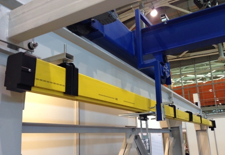
Installation is carried out using scaffolding or special lifts on prepared mounting structures. A system of rail tracks should be organized in which the free passage of the target mechanism along the address loops is ensured. I-beams act as the supporting base. They are mounted to the surfaces of the ceiling or walls, which, in principle, can withstand heavy loads. The installation instructions for this type of busbar trunking indicate that when fixing, the minimum distance between the mounting points of the brackets should be no more than 3 m if a straight-through installation is assumed. In areas with turns or using curved sections, the distance between the fasteners should be no more than 1.5 m.
Particular attention during installation is given to the technical design of maintenance mechanics like carriages and rollers. Firstly, their lines of movement should be clean and smooth - without protrusions, burrs and other defects. Secondly, external non-working surfaces with drive communications and the rear part of movable mechanics are additionally closed during installation of the busbar with complete covers and couplings, for which free space is also previously calculated.
Connecting equipment to the track busbar
Special models of busbars with a track system of connections are intended for the installation of lighting devices. They are distinguished by an optimized and compact suspension system with transitions, due to which it is possible to design conductors of any shape and configuration. Installation and connection of track lights on the busbar are performed in the following sequence:
- The wire base is fastened by installing screws in the holes made with the capture of the base panel or with the help of a hanging bracket on cables.
- A terminal block is being installed through which the track light is subsequently connected.
- If the block is not provided for in the design, it must be integrated using a special module that is suitable in format to the busbar trunking fittings.
- The connection is carried out according to the standard scheme - the gripping screws are unscrewed in the well, after which the wire conductors are inserted and the fasteners are restored to their previous state.
By connecting the track light on the busbar in one section, you can lay its line along the following blocks of the design to the place of entry into the supply transformer. One central connector allows you to create a branched network of energy supply of lamps distributed over long rails of the wire. Also, in the majority of track structures, the possibility of universal extension of the channel length is provided, which is performed by means of special connectors.
Features of mounting open busbars
Almost all types of busbars are made in two versions - with an open and closed loop system. The first option is a lightweight design without external protection. It is recommended to use such equipment in places where there are no aggressive environments of external influence.
Installation is carried out according to a simplified scheme - with the help of bolted joints, suspension cables or mounting plates to the surfaces of communication shafts. However, after mounting open busbars, special cable insulation must be performed. For example, sections of the bus where open insulation is used must be covered with asbestos or similar flame-retardant material, which will also prevent sparks from entering the wiring. External closing covers and panels are not used in such designs.
Features of the installation of closed busbars
These are full-format collapsible modular shafts that close the electric track from all sides. This option can be used in places of increased external loads. The wiring itself at the first insulation level is covered by a multilayer sheath, which prevents the risks of mechanical stress and electromagnetic influence. Outside mounted metal housing made of aluminum or steel alloy. As a fastener for closed busbars, reinforced mounting structures with anchor fixing can be used. Heavy housings are mounted by means of brackets to frames and profile mounting components. As a basis for fastening, surfaces of capital structures, walls, ceilings and partitions are usually used. The operational features of a metal enclosed box can be attributed to the fact that it acts as a grounding circuit that can be connected to the main channels of electrical protection. In open-type systems, this function already in the busbar trunking is performed by special metal rods.
Busbar assembly and installation equipment
The complex of installation measures provides for the implementation at first glance of typical, but still diverse technical operations. At each stage of the work, a certain group of tools and equipment is used. In particular, the following tools and devices are used:
- Manual mounting tool. A basic set of tools, including screwdrivers, hammers, pliers and other tools that will be required to work with fasteners during the assembly of the wire.
- Power tool. To create holes, cut excess busbar trunking and serial tightening of hardware, you will need a drill screwdriver, electric jigsaw, angle grinder, welding equipment, hammer drill, etc.
- Equipment for installation. This is additional equipment for mounting the busbar, through which lifting and hinged fixing of the structure can be performed. In this quality, traverses, grips, winch mechanisms, hoists, crane manipulators, etc. are used.
- Measuring instruments. This tool is used to check the condition of the busbar trunking electrical infrastructure. We are talking about multimeters, testers, ammeters and other devices that measure certain wiring indicators.
Safety measures when installing a busbar trunking
During the installation process, the general requirements of the safety rules during electrical work, as well as special standards related to commissioning activities in relation to conductive modules must be observed. Among them are the following:
- It is forbidden to use busbar designs as load-bearing elements or scaffolds.
- At the time of installation on the assembly and fixing section of the busbar, it is forbidden to be outsiders until the rigid fastening is completed.
- When organizing technical conditions for performing fastening and connecting operations at heights, it is impossible to use devices and devices not intended for safety purposes.
- Special safety requirements for mounting busbars are presented for welding. In particular, such operations should only be carried out by qualified installers. In the welding room itself, flammable objects and materials must be insulated.
Conclusion
Installation of communications with busbars requires considerable technical, power and financial resources. Nevertheless, the organization of such work is a troublesome business, but justifying itself. The protected design of the conductive lines extends the life of the wiring and reduces the risks when it is used in hazardous industries with aggressive working environments. How these and other positive effects will be provided depends on the quality of the work performed. Therefore, immediately after their completion, a comprehensive check of the installation of the busbar trunking is performed, during which possible defects and deviations from design requirements are identified. Mandatory revision of joints, welds, reliability of the general fastening, characteristics of insulators, etc. After that, test work is organized with the measurement of electrical wiring and the busbar is introduced into the operational process.