The means of technical organization of communications are currently of greatest interest to the IT industry. This is manifested both in the development of wireless systems, and in the fundamental filling of electronic devices with the ability to communicate with other equipment, which was not discussed several years ago. But also do not stand still and the traditional physical channels of information transfer. For example, the concept of LVDS (Low-voltage differential signaling) is based on the principles of transmitting low-voltage signals through several differentiated channels. This method of organizing the broadcast bus is highly efficient and does not require large expenses.
Interface Overview
The abandonment of wireless technology in favor of classic channels still provides significant benefits. The point is not even in the stability of data transfer, but in speed and unpretentiousness in terms of service. As for the dynamics, on average, such a line is capable of providing 400-600 Mbit / s on one twisted pair. LVDS technology appeared as a response to requests in solving the problem of transmitting information over long distances. But its significant difference from alternative methods was an unusual scheme of branching contours. After all, what is LVDS in terms of technical and structural implementation? This is precisely a set of differentiated wire channels designed for exchanging data between devices and microcircuits. The hardware itself is not subject to standardization. Equipment can be used, in principle, available for integration of the interface. But conductors do not constitute anything beyond the scope of modern specifications. Moreover, parallel lines can be based on obsolete conductors without fiber optic networks. The essence of technology lies in the way these channels are organized.
Differential signals have a low sensitivity level with a range of 250 to 450 mV. And in the context of considering the parameters of data transmission lines, one cannot ignore the sources of information with which the LVDS interface works. Description of end devices can be expressed in the form of shapers-transmitters, which are executed as current keys. Thanks to this equipment, the signal processing speed is independent of the main voltage in the line. Based on the foregoing, we can draw two intermediate conclusions about the LVDS system:
- In the process of data transmission, a small signal amplitude is assumed with respect to sensitivity parameters.
- Broadcasting is carried out with a current nature.
In practice, the operation of the interface, this means that the system can maintain high speed even with low power dissipation. On specific figures, the theoretical value of the speed will be 1923 Mbit / s, but manufacturers of turnkey solutions still recommend adhering to the level of 655 Mbit / s.
Features of differential channel allocation
To begin with, it is worth considering what a differential signal is in principle. This is a method of transmitting data over electrical networks using antiphase lines. In accordance with the rules for organizing such channels, the signal is broadcast in the form of a differential pair in which each stream has its own conductor. This ensures inversion - that is, two signals with different signs participate in one pair. The cheapest way to implement these pairs is to use twisted conductors, but the use of twinaxial cables and direct wiring on a printed circuit board is also allowed. It is important to emphasize here that the LVDS receiver reacts precisely to the difference between the signals in a pair, and not to the differences between the ground potential and a specific conductor.
Differential couples have a special design. In the diagrams, LVDS signals are designated as RX (0-3), RXC, etc. The output signal labeled CLK reflects the pixel frequency, also determining the spectrum of R / G / B signals on the transmitter. In practice, the differential channel interface can be used to transmit 18 and 24-bit colors. In this regard, the TMDS interface is closest to LVDS, but it does not distinguish between individual differential pairs. In other words, it becomes possible for each pair to assign signals of a certain color spectrum.
Differentiation as a way of transferring control flows deserves special attention. In this case, the signals transmit information with specific circuits and configurations. For example, frame and line synchronization signals are widely used, as well as channels that transmit data resolution information. But is it possible to combine not just disparate pairs with different data, but groups of signals that differ in the type of information contained? Does it depend on the final receiver that the LVDS interface works with? A description of the principle of processing such data can be represented as follows:
- The shift register of the transmitter accepts several groups of information from different differential pairs.
- The receiver converts the data format.
- The control board redistributes the flows again, highlighting the target information.
- The receiver interface adjusts the hardware settings or outputs a signal in the playback area.
Signal Quality Definition
The operation of LVDS-based systems is characterized by the speed and range of information transfer. These are the main quality indicators on which the operational potential of a particular line depends. Under ideal conditions of channel use, there is no external interference and, accordingly, the maximum possible speed and range parameters are reached without restrictions. But since in practice such conditions do not occur, in the process of designing and servicing LVDS interfaces, there is a need to assess their quality.
The most common methods for analyzing differential lines include eye charting. On it, in particular, the level of signal distortion is clearly reflected. There is also a quantitative assessment expressed by the so-called percentage of jitter. In the complex, both characteristics indicate the degree of scatter of photons, which is determined by several factors. The main of them can be called intersymbol interference, which determines the attenuation of the signal and its frequency non-uniformity. Also, the data transmission channels themselves can influence each other. This applies to neighboring lines provided with low-quality insulation. This interference can be minimized by tracing the board.
Channel Composition
A full-fledged line in the LVDS system is formed by the transmitter and the connecting infrastructure, providing a link between the source of information and the receiver. The maximum speed in such a channel is 622 Mb / s, subject to approaching the configuration standard. The connection medium consists of a circuit board and wiring. Moreover, options are also allowed in which one of the components may be absent. But in this case, the LVDS interface will be limited both in range and in the speed of information transfer, even regardless of the influence of external factors.
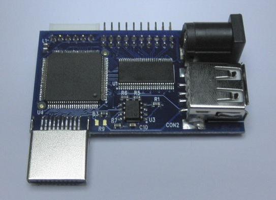
The printed circuit board acts as the base for installing the receiver or transmitter. The integration of termination circuits, connectors for connecting functional components and other auxiliary equipment involved in the operation of the system is also practiced. A key condition for the operability of the complex is the mutual correspondence of all its elements, a sign of which will be the technical possibility of their installation on the tracks of the printed circuit board. Checking for errors in the selection of components for the LVDS channel is performed at the testing stage. Already in the practice of operation, after putting the system into the workflow, eliminating incompatibilities with available tools can require large financial costs and technical resources.
LVDS Cables & Connectors
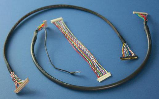
Connecting infrastructure is based on wired circuits and facilities that provide the ability to connect them. In the differential interface, it is recommended to use a symmetrical twisted pair. Such a cable will provide optimal signal characteristics due to the support of constant resistance (of the order of 100 Ohms) and the corresponding influence of pickups at the end of the receiver. At the same time, the LVDS cable and its parameters are not strictly regulated. The exception may include certain wire operating parameters, breakdown configuration by contact points, etc. In the choice of cable, a lot depends on the specific requirements of the system. For example, a distance of up to 50 cm allows the use of almost all types of wired media. A distance of 10 cm is preferably served by a twisted pair of CAT3-5 standards. The speed in such an infrastructure will be up to 400 Mbps.
The connectors used to create the LVDS links are also selected based on the design requirements for the system. But in almost every case, the emphasis is on the possibility of servicing a high-speed data channel taking into account electromagnetic radiation and external interference. Particular attention is paid to the location of the lines on the contacts. The input interface may have different connector configurations that differ in length and potential distortion. The construction of lines requires the use of conclusions corresponding to the wires of one pair. This will allow you to balance speed performance while optimizing interference with additional tools.
In practice, creating differential channels with connectors, pinout is one of the key technical parameters. It is important to consider it when connecting the final receiver with the matrices. At a basic level of performance, 30-pin interfaces can be used. But modern devices, which impose ever-increasing demands on line throughput, are guided by LVDS pinout on a 40-pin. This connector can be single or dual channel - this nuance should also be borne in mind when organizing the connection.
Data flow management
For the effective use of differential channels, it is not enough to choose the appropriate functional components for the characteristics. The task of supplying data streams is solved at the stage of developing the configuration of high-speed lines. The designer builds a platform with separate transmitters, sometimes involving serializer chips. These are special signal converters that provide parallel-serial distribution. On the other hand, at the end of the receiver, a deserializer is installed that performs the inverse transformation from serial to parallel. Using serializers in practice allows optimizing the frequency of a high-speed channel to values acceptable for the target device.
A method of controlling information flows is also applied by means of receivers and transmitters integrated into the equipment. For example, Xilinx integrates multiple ports into a programmable LVDS interface to host components of the same standard. This solution has a significant advantage in the form of optimization of the device design, which facilitates the construction of the target channel architecture taking into account the required speed indicators, regardless of the implementation of the external interface.
LVDS application
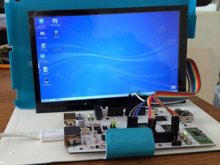
The development of technology is due to increased requirements for the transmission of video information. The configuration of the channel device of this differential interface is optimal for servicing office and home appliances that work with photo, video, 3D-graphics and other multimedia materials. Moreover, computers, network distributors, and even satellite communication systems can act as terminal devices. That is, the LVDS interface and its application can be called universal in terms of integration capabilities in modern systems for the transmission and processing of digital information. The most common area of technology use is the connection of monitors with a PC and other sources of information. For example, for high-resolution LCD panels, LVDS buses are used with low power consumption but wide bandwidth.
To organize high-speed data streams , microcircuits are used that are able to convert 21-48 bit data to a multi-channel LVDS system with subsequent output to a clock signal. Similar configurations are used in the maintenance of superfast servers and routers. In general, it can be said that low-voltage differential signaling is suitable for multipoint systems, the components of which must be coordinated from different ends of the information transfer. Some LVDS converters find their place in the industry, acting as random data keys.
LVDS system in monitors and matrices
The standardized interfaces for connecting video playback devices as the main functional component just use the connectors. It is enough to choose the optimum input for the characteristics and a connecting line will be organized. In selecting a connector for a particular equipment, the following characteristics are taken into account:
- Resolution of the monitor or matrix.
- Screen size.
- Frame rate, etc.
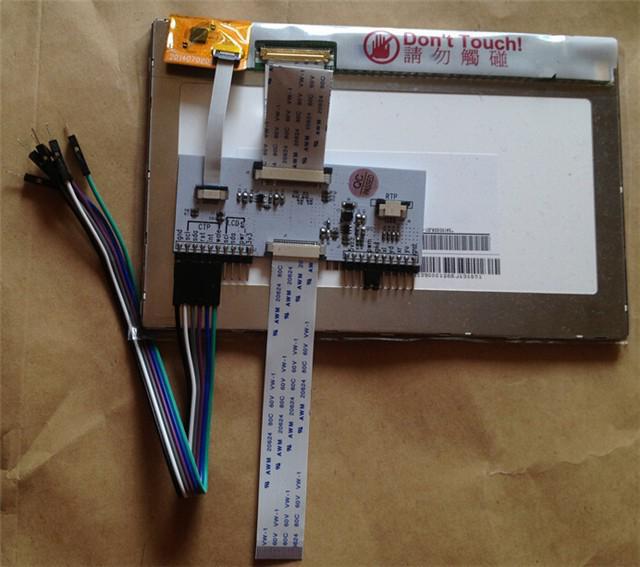
The above pinout, for example, is largely dependent on the diagonal. So, the LVDS interface for 8 inches can very well be introduced into the infrastructure through a 20-pin contactor. The increase in contacts can occur not only on the central side, but also on the sides. Typically, these "pins" perform the function of grounding.
An established interface provides voltage for the matrix components, which also differs depending on the screen size. Typically, an initial value of 3.3 V is enough for 15-inch devices or less. The 12 V standard supplies 19-inch matrices, etc. When connected, transmitters with receivers can also be inserted. In modern panels, they are implemented as microcircuits, but sometimes they are also included in the composition of scalers, that is, LVDS interface controllers. Wiring diagrams with this addition include the use of a 30-pin connector at a minimum. The distribution of signals by “pins” will provide for classification into three main groups:
- VCC - supply voltage.
- VSS - grounding.
- RX is the input of one of the differential pair.
Benefits of Using LVDS
One of the main advantages of this interface is the ease of management, coordination and switching. Most modern high-speed lines involve the use of special materials both for the manufacture of the same cables and for signal control. In the case of differential channels, the simplest standards are applied, which also expand the possibilities of using the technology. A typical laptop matrix based on LVDS can provide fast transmitter switching to the maximum level of performance with increasing signal processing speed. At the same time, energy costs are kept at low or medium rates relative to competitive data lines. Optimization in this part is achieved by reducing the power of the dissipated load - not more than 1.2 mW at an impedance of 100 ohms. Some component manufacturers for LVDS also focus on statistical power consumption. The economic factor is attractive in terms of the cost of the components from which the infrastructure is formed. Using the same twisted pair cable in comparison with optical fiber is completely incomparable in terms of costs both during purchase and in maintenance costs.
Part of the advantages is due to the use of the differential method of signal translation as such. We can distinguish both the simplicity of information transfer schemes and low sensitivity to interference. Of course, if you do not take into account the radiation in adjacent closely spaced channels. The sensitivity of the LVDS interface is also not critical when operating in strong magnetic fields. Correction of the gables does not affect the quality of the transmission, so the noise is stored within acceptable values.
Conclusion
The architecture of the majority of turnkey solutions based on the LVDS technology platform is characterized by productivity, economy and flexibility in terms of changing the functional configuration. This combination of positive operational properties was achieved by combining the best qualities of a traditional parallel interface (in the latest versions - digital) and the principles of serial connection. As a result, the reduction in the number of conductors allowed the system to be used in compact devices that require support for high-quality signal transmission.Actually, the matrix for a laptop based on LCD-controllers demonstrates the full range of technology advantages. Such solutions are being developed by companies such as Samsung, Philips, HP , etc.
, -. , , . , , . , LVDS , – , . , , . , .