In apartments and private houses, one electric meter is installed, according to which payment for consumed energy is calculated. It is simply considered that in everyday life only its active component is used, although this is not entirely true. The modern dwelling is full of devices in the schemes of which there are elements that shift the phase. However, the reactive power consumed by household appliances is incomparably less than that of industrial enterprises, therefore, it is traditionally neglected when calculating payment.
A plant or factory, the management of which does not monitor the consumption of stray currents passing through the load circuit, causes great harm to the energy systems of the region and the country as a whole. The air around the power transmission line is completely useless; windings of transformers installed in substations may not withstand loads, especially during peak periods.
Inductive and capacitive load
If you take a conventional heating device or a light bulb, then the power indicated in the corresponding inscription on the bulb or nameplate will correspond to the product of the current flowing through this device and the mains voltage (we have 220 Volts). The situation changes if the device contains a transformer, other elements containing inductors, or capacitors. These parts have special properties, the graph of the current flowing in them lags or ahead of the sinusoid of the supply voltage - in other words, a phase shift occurs. An ideal capacitive load shifts the vector by -90, and inductive - by +90 degrees. Power in this case is the result of not only the product of the current by the voltage, a certain correction factor is added. What does this lead to?
Geometric reflection of the process
From the school course of geometry, everyone knows that the hypotenuse is longer than any of the legs in a right triangle. If active, reactive and apparent power form its sides, then the currents consumed by the coil and capacitance will be at right angles to the resistive component, but with directions in opposite directions. When adding (or, if you wish, subtracting, they are of different sign) values, the total vector, that is, the total reactive power, depending on what kind of load prevails in the circuit, will be directed up or down. By its direction it is possible to judge what kind of load prevails.
Reactive power during vector addition with the active component will give the full amount of power consumption. It is graphically depicted as the hypotenuse of a power triangle. The more this line will be hollow in relation to the abscissa axis, the better.
Cosine phi
The graph shows that the angle φ is formed by two vectors, full and active power. The less their values differ, the better, but reactive power, which is considered parasitic, interferes with their full merger. The larger the angle, the higher the load on the power lines, increasing and decreasing the transformers of the power supply system, and vice versa, the closer the vectors are inclined to each other, the less wires will be heated throughout the circuit. Naturally, something had to be done with this problem. And the solution was found, simple and elegant. Mutual compensation of reactive power allows you to reduce the angle φ and maximize bring its cosine (which is also called the power factor) to unity. For this, it is necessary to lengthen the vector of the capacitive component so as to achieve a resonance of the currents at which they "cancel out" each other (ideally completely, but in practice - to the greatest extent).
Theory and practice
All theoretical calculations have value the greater, the more applicable they are in practice. The picture at any developed industrial enterprise is as follows: most of the electricity is consumed by motors (synchronous, asynchronous, single-phase, three-phase) and other machines. But there are also transformers. The conclusion is simple: in real production conditions, inductive reactive power prevails. It should be noted that the enterprises install not one electric meter, as in houses and apartments, but two, one of which is active, and the other - it is not difficult to guess which one. And for the excessive use of energy “driven” by power transmission lines in vain, the relevant authorities are mercilessly fined, so the administration is vitally interested in calculating reactive power and taking measures to reduce it. It is clear that one cannot do without electric capacitance in solving this problem.
Theory Compensation
From the graph given it is quite clear how to achieve a reduction in stray currents up to their complete elimination, at least theoretically. To do this, in parallel with the inductive load, turn on the capacitor of the corresponding capacitance value. The vectors add up to zero, and only the useful active component remains.
The calculation is made according to the formula:
- C = 1 / (2πFX), where X is the total reactance of all devices connected to the network; F is the frequency of the supply voltage (with us - 50 Hz);
It seems to be - what is easier? Multiply “X” and the number “pi” by 50 and divide. However, everything is somewhat more complicated.
And how in practice?
The formula is simple, but determining and calculating X is not so simple. To do this, you need to take all the data about the devices, find out their reactance, and in vector form, and even then ... In fact, no one does this, except for students in laboratory work.
It is possible to determine reactive power in another way, using a special device - a phase meter indicating the cosine phi, or by comparing the readings of a wattmeter, ammeter and voltmeter.
The matter is complicated by the fact that in a real production process, the load value is constantly changing, as some machines turn on during operation, while others, on the contrary, are disconnected from the network, as required by the technological regulations. Accordingly, ongoing measures are needed to monitor the situation. During night shifts, lighting works, in the winter air can be heated in the shops, and in the summer it can be cooled. One way or another, reactive power compensation is based on theoretical calculations with a large share of practical measurements of cos φ.
Connecting and disconnecting capacitors
The simplest and most obvious way to solve the problem is to put a special worker near the phase meter who turns on or turns off the required number of capacitors, achieving the minimum deviation of the arrow from unity. So at the beginning they did, but practice has shown that the notorious human factor does not always allow us to achieve the desired effect. In any case, the compensation of reactive power, which is most often inductive in nature, is done by connecting an electric capacitance of the appropriate size, but it is better to do this automatically, otherwise a negligent worker can put his own company under a large fine. Again, this work cannot be called qualified, it lends itself to automation. The simplest circuit includes an optical electronic pair of an emitter and a light receiver. The arrow has blocked the minimum value, which means you need to add capacity.
Automation and smart algorithms
Currently, there are systems that can reliably keep cos φ in the range from 0.9 to 1. Since the connection of capacitors in them is discrete, it is impossible to achieve the ideal result, but the economic effect of an automatic reactive power compensator still gives a very good one. The work of this device is based on intelligent algorithms that provide work immediately after switching on, most often even without additional settings. Technological advances in computer technology make it possible to achieve uniform connection of all stages of capacitor banks in order to avoid premature failure of one or two of them. The response time is also minimized, and additional chokes reduce the voltage drop during transients. The modern enterprise power control panel has an appropriate ergonomic layout, which creates the conditions for the operator to quickly assess the situation, and in the event of an accident or failure, he will receive an immediate alarm. The price of such a cabinet is considerable, but it’s worth paying for it, it brings benefits.
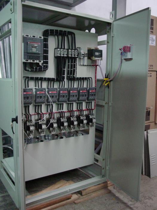
Compensator device
The usual reactive power compensator is a standard-sized metal cabinet with a control and control panel on the front panel, which usually opens. At the bottom of it are sets of capacitors (batteries). This arrangement is due to a simple consideration: the electrical capacitance is quite heavy, and it’s quite logical to strive to make the structure more stable. In the upper part, at the level of the operator’s eyes, are the necessary control devices, including a phase indicator, with which you can judge the value of the power factor. There is also a different indication, including emergency, controls (on and off, switch to manual mode, etc.). An assessment of the comparison of the readings of the measuring sensors and the generation of control actions (connecting capacitors of the desired rating) is performed by a circuit based on a microprocessor. Actuators work quickly and silently, they are usually built on powerful thyristors.
Approximate calculation of capacitor banks
In relatively small enterprises, the reactive power of the circuit can be roughly estimated by the number of connected devices, taking into account their phase-shifting characteristics. So, a conventional asynchronous electric motor (the main “hard worker" of factories and plants) with a load equal to half its rated power has a cos φ of 0.73, and a fluorescent lamp - 0.5. The parameter of a contact welding machine ranges from 0.8 to 0.9, the arc furnace operates with a cosine φ equal to 0.8. The tables at the disposal of almost every main power engineer contain information on almost all types of industrial equipment, and reactive power compensation can be pre-set using them. However, such data serves only as a basis on the basis of which it is necessary to make adjustments by adding or disconnecting capacitor banks.
Nationwide
It may seem that the state has assigned all the care about the parameters of the electric networks and the uniformity of the load to it to factories, plants and other industrial enterprises. This is not true. The country's energy system controls the phase shift on a national and regional scale, right at the exit of its special product from power plants. Another question is that the compensation of the reactive component is carried out not by connecting capacitor banks, but by a different method. To ensure the quality of energy supplied to consumers in the rotor windings, the bias current is regulated, which is not a big problem in synchronous generators.