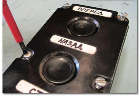
The start-stop control buttons are quite common in production. These devices are used to start the machines. Before connecting the model, it is important to know the type of switch. There are contact and wireless modifications. Additionally, the controller that is used during installation plays the role. To understand this issue, first of all, you need to consider the standard switch connection scheme.
Wiring diagram
The standard connection diagram for the start-stop button involves the use of a closing contactor. Triggers are selected with conductivity from 4.5 See. Some experts install devices directly through a relay. Only wired modifications are suitable for this. If you place the devices with a comparator, then the trigger is used with insulators. The first wires from the switch are closed on the relay coil. The contactor is connected directly to the transceiver.
Review of QF1 circuit breakers
The starter is connected via the start-stop button using a relay. If we consider a circuit with a wired controller, then the thyristor is used in two phases. Directly a capacitor is required at 4 pF. Experts say that regulators can be used on two and three outputs. However, in this case, a lot depends on the type of rectifier. In standard machines, it is installed with a positive charge.
Its resistance is at least 50 ohms. It is also important to note that it has a locking plate. In such a situation, the first contacts from the switch are connected to the relay. In this case, the controller closes in the first phase. Before checking the resistance, it is important to make sure that the circuit is grounded. It is also recommended to pre-connect the insulator. The second contact from the switch is connected to the expander. A stabilizer for connection will require a wave type.
Non-reversible starter circuit
Irreversible starters are often found recently. Connection of the start-stop buttons is allowed to be done directly through the relay. In this case, triggers are not applied. It should also be noted that the installation of the switch can be done through a comparator. In such a situation, it will be possible to install the regulator. Additionally, a stabilizer is installed.
Experts say that the converter is used bi-directional type. The first contact is connected in the first phase. It should also be noted that capacitors in the circuit are capacitive type. In this case, the stabilizer will need a single-pole type. If we consider two-channel converters, then only contact expanders are used for them. The switches in this case are closed with a lining. The first contacts are connected in the second phase.
The use of reversing starters
The start-stop button is connected via reversing starters with and without converters. If we consider the first option, then capacitors are used with semiconductor insulators. The winding itself is used at 15 V. The resistance index on it should be at least 30 ohms.
The comparator for the switch is used on two outputs. The first contact closes in the first phase. The stabilizer must be in the open state. Some modifications are sold with filters. It is also worth noting that there are contactors with single-junction resistors.
Instructions for starters PML-1100
How to connect the start-stop button? This is quite simple to do through a channel thyristor. Converters for the device are selected on two filters. The average resistance is 55 ohms. Dinistors are allowed to use the bidirectional type.
Experts say that it is important to clean contactors carefully. Additionally, it is worth noting that the conductors must be well insulated. The first contact closes in the second phase. The average conductivity of the circuit is 4.5 cm. The expander, when installed, uses a broadband type.
Connecting a modular starter
Only the wired start-stop button is connected to the modular starters. In this case, converters are often used with adapters. The first contact from the switch closes in the first phase. Directly the insulator is installed last. The thyristor is used with a rectifier. However, in this case, much depends on the controller. If we consider models with three outputs, they have two dinistors. The first contact from the switch closes in the second phase. The stabilizer at the end is installed with one filter.
Open Actuators
The start-stop button in the housing connects to an open type starter with a wire trigger. The transceiver is used with one or more expanders. When connecting the converter, the resistance is checked, since the capacitor may not withstand the current load.
This parameter averages 33 ohms. If you install a switch with a three-pin controller, the transceiver is used multi-channel type. Its conductivity should be approximately 4.5 cm. In addition, it is important to note that the second contact from the switch closes in the first phase. Experts say that the conductor on the plate must be carefully clamped. The insulator is installed behind the expander. If you solder the feed-through transceiver, then two filters are used for the circuit.
Connection of closed-circuit starters
The start-stop button for these starters is installed directly through the relay. Transistors for this purpose select low conductivity. Before connecting components, the output impedance is tested. The specified parameter in the circuit must not exceed 45 ohms. At high overloads, it is recommended to change the filter. It is also worth noting that problems can be observed due to the low conductivity of the transistor. The first contact from the switch closes in the first phase. The stabilizer for the circuit is used only single-pole type. The threshold overload indicator for the presented component is at least 5 A.
Connecting a switch via a single junction trigger
Single junction triggers are highly conductive. Insulators for devices are selected bidirectional type. A simple start-stop button is installed directly through the relay. It should also be noted that the installation of the device can be done through the control unit. If we consider a conventional milling machine, then the transceiver uses a single-channel type. The first contact from the switch is connected in a second phase. At this stage, it is important to test the output impedance. With an overload of 3 A, the conductivity should not exceed 5.5 cm.
If semiconductor controllers are used, the average resistance is 55 ohms. It is also important to note that closing contactors are often installed on two outputs. In this situation, the insulator is installed behind the converter. Thus, overload will ultimately not exceed 6 A. Triggers are often used with an expander. Contacts to them are allowed to connect directly.
Using two-junction triggers
Quite often, the start-stop button is installed with two-period triggers. They are connected via a 12 V relay. The power supply is of a pulse type. The relay can be used at 4 A. The trigger for installing the switch is mounted behind the converter. The output resistance is not more than 40 ohms. If the element is very overheated, then the problem lies in the overload of the trigger. For this, only wired capacitors are used. In this case, the comparators are closed in the first phase.
Devices with capacitive controllers can only be connected via dinistors. In this case, modifications to only three outputs are suitable. The insulator is installed at the output of the circuit. In this case, the converter is selected with a bi-directional lock. The output voltage in the circuit is about 15 V. In this case, the overload factor should not exceed 4 A. If a dipole controller is used, then the adapter can be used on two outputs. The first contact from the switch closes in the second phase. In this case, the resistance should be no more than 30 ohms.