Heating and water supply systems today are at an unprecedented level of technological development. Even at home, an ordinary private trader can organize an efficient and easy-to-manage autonomous heating system using special equipment. Moreover, if the inclusion of power units is partial, then in principle it will not be possible to do without full-fledged means of distributing flows. And the key element of this control fittings is the collector unit, which performs several tasks at the same time, helping to increase the reliability and safety of the heating infrastructure as a whole.
Device purpose
The main function of the plumbing manifold is to distribute the coolant across several heating circuits. For example, if it is planned to organize a heating system in the house with several groups of consumption points in the form of batteries and radiators, then the collector will set the direction to each of them. In addition, at a higher level of distribution, this node can coordinate flows between the water supply, heating and technical and economic support systems, for example. The functionality of the device can be expanded due to the task of mixing flows. Such capabilities are endowed with a collector-mixing unit, in which a unit is provided for receiving a working medium with different temperature conditions. The mixing function as such is required to change the temperature of the exhaust stream. So, if the flow initially leaves the boiler at 85-90 ° C and it is impractical to lower it already for other reasons of hot water supply, then, for example, for a heat-insulated floor that runs on a heat carrier with a mode of 30-45 ° C, special water treatment will be required by blending.
Manifold design
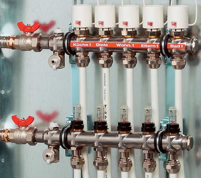
The device is formed by one or more pipes located parallel to each other and providing branch pipes for connection with different branches of the water supply or heating system. A node can combine several collectors - for example, a configuration with separation of the supply and return distribution blocks is very convenient. The list of control and connecting accessories includes thermostatic valves, shut-off elements, taps, drain valves, etc. Additional functionality of the manifold assembly can be represented by air vents, manometers, thermometers and filters with a drainage system. Moreover, some manufacturers also offer circulation pumps that operate directly on the collector block as an option for high-capacity systems.
Key Features
There are many structural and functionally different options for the execution of collectors. The average performance characteristics of most models are as follows:
- The material of construction is brass or stainless steel. It is possible that the use of plastic and copper fittings, not to mention rubber seals.
- Operating temperature - from 70 to 130 ° C. For use in an apartment, the collector assembly is designed for a heat load of up to 95-100 ° C.
- The number of outlet pipes is from 2 to 10. Also, the possibility of expansion by increasing the supply circuits of the assembly is not excluded.
- Pressure - from 10 to 16 bar.
- The valve diameter is usually 1/2 or 3/4 inch.
- Throughput - from 2.5 to 5 m3 / hour.
Features of the collector unit for underfloor heating
The underfloor heating system is an example of the local distribution of flows through the collector comb, in fact, within a single point of consumption. From here comes a number of features of the organization of the distribution group:
- Due to the low power load, the requirements for the material of manufacture are reduced, so specialized collectors for floor heating systems can be made of polypropylene.
- The need to lower the temperature regime. As already noted, the collector-mixing unit for a warm floor pre-converts the hot flows, bringing the temperature to 30-45 ° C. But this condition is not always required - depending on the material of manufacture of the pipeline.
- Uniform flow distribution. Underfloor heating is mounted with the expectation of the same length and throughput in all circuits. For the collector, this means the possibility of the same device and adjustment of the exhaust pipes with valves.
- Be sure to install flow meters and manometers on each drain.
Assembly assembly
It is advisable to initially purchase the distribution nodes in the assembly, which will eliminate installation errors, but independent layout has its advantages. For example, you can take into account individual technical features and make appropriate corrections for them. How to assemble a collector assembly in order to avoid mistakes and take into account the nuances of a particular application? Assembly is carried out on the basis of "native" components or parts that are suitable for the characteristics. Joining elements is necessary with the use of seals and sealants, which will increase the reliability of the joints. Do not ignore the manufacturer's recommendations - for example, with regard to the permissible tightening torque of the fittings, it will give the most accurate indicators of the tightening torque in relation to specific parts. Lastly, the installation of auxiliary and optional devices - measuring instruments, pump, air vent, etc.
Collector mounting
The integration of the device into the heating system with connection to the mains is carried out in the following order:
- The return and supply pipes are released.
- The external thread is cleaned on the connection pipes and manifold pipes.
- If the design does not provide for sealing rubber rings, then you must independently apply sealant, flax fiber, or FUM tape on the thread.
- On the prepared branch pipes ball valves are installed. Installation of the collector assembly to the branches from the riser or other main channels begins.
- The fasteners of the drives with cranes are tightened to a sufficient degree of sealing. Again, indicators of lingering effort in each case are individual.
- The balancing valve is connected, plugs and impulse tubes are installed, if any, are provided in the project.
Connecting the node to the pipes of consumers
When the collector is fixed and connected to the central pipeline, you can connect it to the communications of the same batteries and radiators. A similar treatment of threaded joints with the application of sealing and sealing materials is preliminarily performed. In this part, due to differences in the throughput of heating equipment, the creation of transition sections with repair inserts may be required. It is advisable to mount the collector unit adapters using PEX pipes and polypropylene fittings. When connecting the supply pipes, it is better to use a sliding sleeve system, which will increase the reliability of the circuit in terms of resistance to vibration in conditions of intensive circulation.
General installation recommendations
When performing the installation work of the collector block, the following rules should be followed:
- It is only possible to start installing the unit in the water supply or heating system after checking the communications by crimping.
- At the time of installation, the supply line from the riser must be freed from the coolant.
- When connecting the collector assembly to third-party pipes, regardless of their purpose, the alignment between the return and supply circuits must be maintained.
- When performing installation, adjustable spanners and wrenches are used, but not their pipe counterparts.
- Fill the mounted collector with water gradually, minimizing the risks of water hammer.
Commissioning activities
Before putting the device into operation, several adjustments should be made. First of all, it is necessary to establish a pressure indicator taking into account possible differences. This is usually done on the DPV valve, after which the nominal water flow rate in the STP valve is set. In the future, the work of the collector unit for heating will be controlled through a thermostatic head (in modern versions). In it, with an accuracy of 1 ° C, the current temperature regime is set. In more developed models of the regulatory system, it is possible to programmatically with intelligent control algorithms, which take into account the microclimate indicators in the complex.
Device Maintenance
Under the condition of intensive use of the heating system, it is recommended to check the collector for leaks and the condition of functional organs every month. Measuring devices and flow meters are checked for accuracy of readings, and connections for reliability. Defective collector assembly elements should be replaced with their equivalents with the same performance characteristics. As a rule, this applies to consumables, gaskets, knobs of regulators and valves. You should also periodically balance the system. This is done through tuning valves with flow meters.
Conclusion
Heating systems in private homes, and increasingly in apartments with floor heating, are constantly expanding due to the inclusion of new functional components. On the one hand, such an overload does not have the best effect on the size of the heating infrastructure, and on the other hand, each innovation increases the reliability and efficiency of the system. As for the collector, it can become a good base for placing such functionality. Along with the key functions of the distribution and mixing of flows, the fully assembled collector assembly will also serve as a means of cleaning, venting, and supporting the circulation of flows. Of course, such an acquisition will cost a lot, especially when it comes to models from firms such as Wilo or Valtec. But, as the reviews of the users themselves show, a properly organized distribution and mixing unit will pay off both in terms of performance and for reasons of energy saving.