What are current clamps, and what measurements can be made with their help? How to use them to the maximum? Which current clamps are best suited to specific conditions? This review is intended to provide answers to all these questions.
With the introduction of technological advances in electrical equipment and circuits, new problems arise for electricians and technicians. Progress requires not only great opportunities from modern measuring instruments, but also great skills from the people who use them. Electricians with a good knowledge of the basics of using test equipment are better prepared for metering and troubleshooting. Current clamps are one of the most important and common tools that can be found today in their arsenal.
This device is a measuring device in which a voltmeter and a tick-type ammeter are combined. Like a multimeter, having gone through the analog period, it entered the world of digital measurements. Created primarily as a universal tool for electricians, modern models have become more accurate and have gained many additional features, some of which are very special. Today, current clamps duplicate many of the basic functions of a digital multimeter, but differ from it by the presence of an integrated current transformer.
Principle of operation
The ability to measure large alternating currents with current clamps is based on the simple operation of a transformer. When the clamps close around the conductor, the current is in the device like the iron core of a power transformer, and flows through a secondary winding connected through an input shunt. A significantly lower current is supplied to the input of the device due to the ratio of the number of turns of the secondary winding to the number of turns of the primary. Typically, the primary winding is represented by a single conductor around which pincers are clamped. If the secondary winding has 1000 turns, then the secondary current is 1/1000 of the primary, or, in this case, conductor. Thus, 1 A is transformed into 0.001 A or 1 mA at the input of the device. This method makes it easy to measure large currents, increasing the number of turns of the secondary winding.
The choice
The purchase of current clamps requires not only familiarization with their specifications, but also an assessment of their functionality and quality, provided by the design of the device and the technology of its production.
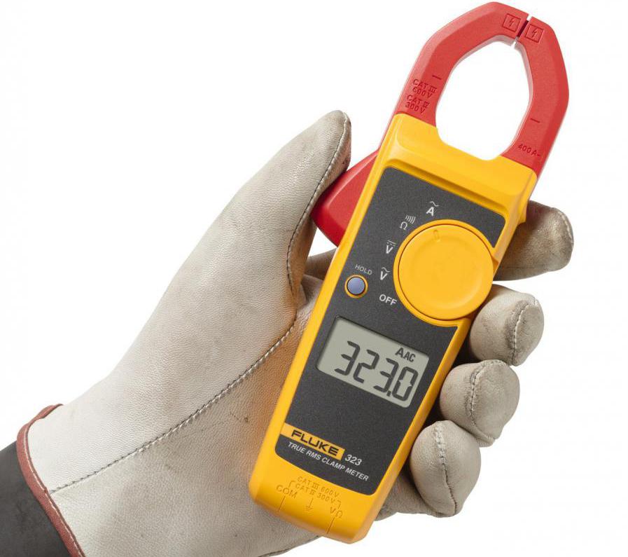
The reliability of the tester, especially in difficult conditions, is more important today than ever. Engineers, developing measuring instruments, must test them not only for electric, but also for mechanical strength. For example, Fluke current clamps undergo a rigorous testing and evaluation program before being shipped to stores.
User safety should be a primary consideration when choosing this instrument or any other electrical measuring equipment. In addition, digital clamp meters must not only be manufactured in accordance with the latest standards, but each instrument should be tested and certified by testing laboratories such as UL, CSA, VDE, etc. Only in this case, you can be sure that the instrument Meets all new safety requirements and standards.
Resolution and measuring range
The resolution of the instrument indicates how accurate its measurements are. It determines the minimum signal change that can be detected. For example, if the resolution of the current clamp is 0.1 A in the range of 600 A, then a current of about 100 A is measured with an accuracy of 0.1 A.
Who needs a ruler marked in centimeters if you need to determine the size of an object several millimeters in size? Similarly, you should choose a device that can display the required resolution.
Error
This is the maximum allowable error that may occur under certain operating conditions. In other words, this is an indicator of how closely the measured value matches the actual.
Instrument error is usually expressed as a percentage of the reading. For example, if it is 1%, then for 100 amperes the actual current value is in the range from 99 to 101 A.
In addition to the error in the specifications, it can indicate how much the reading in the rightmost digit of the measured quantity changes. For example, if the error is indicated as ± (2% + 2), then for 100.0 A the actual current is in the range of 97.8–102.2 A.
Amplitude factor
With the growth of electronic power supplies, the currents obtained from modern distribution systems are no longer pure 50-Hz sine waves. They have become quite distorted due to the harmonics that these power sources generate. However, the electrical components of the network, such as fuses, busbars, conductors and thermal elements of circuit breakers, are designed for RMS current, since their main limitation is associated with heat transfer. If it is necessary to check the electric circuit for overload, then you need to measure the rms current and compare the obtained value with the nominal. Therefore, modern test equipment should be able to accurately measure the true value of the signal, regardless of the degree of distortion.
The amplitude coefficient is the ratio of the peak current or voltage to their rms value. For a pure sine wave, it is 1.414. However, a signal with a very sharp pulse will cause the amplitude coefficient to be high. Depending on the width of the pulse and its frequency, coefficients of 10: 1 and higher can be observed. In real energy distribution systems, amplitude coefficients of more than 3 are rarely found. Thus, the amplitude coefficient is a sign of signal distortion.
Measurement data can only be made by instruments that are capable of measuring the true rms value. It shows how distorted the signal can be and register it in accordance with the error of the instrument. Most current clamps are capable of measuring amplitude coefficients of 2 or 3. This is sufficient for most cases.
Alternating current
One of the main purposes of current clamps is AC measurement. Typically, such measurements are carried out on the branches of the electrical distribution system. Determining the current flowing through various circuits is the routine of an electrician.
To carry out the measurement it is necessary:
- Select AC mode.
- Open the pincers and close them around one conductor.
- Read the readings on the display.
By measuring the current along a section of the circuit, it is easy to determine how much power each load takes.
When the circuit breaker or transformer overheats, it is best to measure the load current. However, make sure that true rms values are recorded to accurately measure the signal heating these components. A conventional device will not give a true reading if the current and voltage are not sinusoidal due to non-linear loads.
Voltage
Another common function of the instrument is voltage measurement. Modern current clamps are capable of determining direct and alternating voltage. The latter is usually created by a generator and then distributed across the network. The job of an electrician is to be able to take measurements throughout the power supply system in order to find troubleshooting. Another use of the device is to check the battery charge. In this case, it is necessary to measure direct current or constant voltage with current clamps.
Troubleshooting a circuit usually starts by checking the network settings. If there is no voltage, if it is too high or too low, this problem must be solved before continuing the search.
The ability of current clamps to measure alternating voltage is affected by the frequency of the signal. Most testers of this type can accurately determine this parameter at frequencies of 50-500 Hz, but the range of the digital multimeter reaches 100 kHz and higher. This is why measuring the same voltage with testers of different types gives different results. A digital multimeter allows you to connect a high-frequency voltage to the circuit, while current clamps filter out the part contained in the signal above their passband.
When troubleshooting a variable frequency drive, the input bandwidth of the instrument may be important to obtain meaningful reading. Due to the high content of harmonics in the signal coming out of the frequency converter, the digital multimeter, depending on its input band, will measure most of the voltage. Registering a variable frequency drive is not a common task. The motor connected to the frequency converter responds only to the average value of the signal, and to register this power the input passband of the tester should be narrower than that of the multimeter. Fluke 337 current clamps are specifically designed to test and troubleshoot this type of fault.
To measure voltage should be as follows:
- Select the appropriate current clamp mode: DC Volts DC (V) or AC Volts AC (V ~).
- Connect the black wire of the test probe to the COM input jack, and the red wire to the V socket.
- Touch the probe tips to the circuit on opposite sides of the load or power source (parallel to the circuit).
- Read indications, paying attention to the unit of measurement.
- Press the HOLD button to fix the result. After that, you can disconnect the probes from the circuit and read the readings at a safe distance.
Measuring the voltage at the input of the circuit breaker before and after connecting the load allows you to determine its drop. If it is significant, then this indicates how well the load is functioning.
Current clamp: resistance measurement instruction
Resistance is measured in ohms. Its value can vary from a few milliohms in contacts to billions of ohms in insulators. Most current clamp meters measure resistance with a resolution of 0.1 ohms. When its value exceeds the upper limit or the circuit is open, OL appears on the display.
This parameter must be measured with the power off, otherwise the device or circuit will be damaged. Some devices provide protection in the resistance measurement mode in case of contact with voltages. For different models, the level of protection can vary greatly.
Most often, the electrical resistance of a contactor coil is required.
The measurement procedure is as follows:
- Disconnect power to the circuit.
- Select resistance measurement mode.
- Connect the black wire of the probe to the COM jack, and the red wire to the Ω jack.
- Touch the probe tips on both sides of the elements or section of the circuit for which resistance is to be determined.
- Read instrument readings.
Circuit integrity
This is a quick check for resistance, thanks to which you can determine the open circuit.
The current clamp with an audible signal allows you to easily and quickly perform many such tests. The device signals when it detects a closed circuit, therefore, when checking, you do not need to look at the display. The resistance level required to trigger the device may be different. A typical value is not exceeding 20-40 ohms.
Special functions
A fairly popular functionality of current clamps, according to users, is the determination of the frequency of alternating current. To do this, close the “jaws” around the conductor and enable the frequency measurement mode. The signal frequency appears on the display. This function is very useful for determining the source of harmonics problems in the electrical network.
Another feature of some models (for example, the Mastech MS2115B current clamp) is the recording of minimum and maximum values. When this function is activated, each measurement is compared with previously saved readings. If the new value is higher than the maximum, then it replaces it. The same comparison is performed for a minimum reading. While the MIN MAX function is active, all measurements are processed in this way. After some time, you can call each of these values on the display and determine the largest and smallest readings for a certain period of time.
For electricians who deal with engines, the ability to capture the current consumed by the motor during its start up can tell a lot about its condition and load. Current clamps of Fluke 335, 336 and 337 can measure it "in movement". To do this, close them around one of the input wires of the motor, activate the in-rush mode and turn on the engine. The instrument display will show the maximum current consumed by the motor during the first 100 ms of its start cycle.
Uni-T UT210E current clamps allow you to determine the presence of an alternating voltage or electromagnetic field in a non-contact manner. To do this, bring the device closer to a distance of 8–15 mm from the test object. The device distinguishes 4 voltage levels, gives an appropriate sound signal and indicates the field intensity with a light indicator.
Current clamp DT-3347 supports temperature measurement function.
Security
Safe measurement begins with the selection of the appropriate instrument for the environment in which it will be used. Once the correct tool is found, it should be used in accordance with the recommended procedure.
The International Electrotechnical Commission has set new safety standards for working with electrical systems. It must be ensured that the instrument used is in accordance with the IEC category and the voltage rating approved for the environment in which the measurement is to be performed. For example, if measurements are made on a 480-volt electrical panel, then category III current clamps should be used for 600 V. This means that the input circuit of the device is designed to withstand the transient voltages usually occurring in this environment, without harming the user. Choosing a tool of this class, which is also certified in UL, CSA, VDE or TUV, means that it has not only been developed in accordance with IEC standards, but has been independently tested and complies with these standards.
Safety regulations
- It is necessary to use current clamps that comply with accepted safety standards for the environment in which they will be used.
- Before taking a measurement, check the probe wires for physical damage.
- Make sure the integrity of the wire using current clamps.
- Do not use probes with uninsulated connections and lack of finger protection.
- Only devices with recessed input sockets must be used.
- Current clamp must be in working condition.
- Always disconnect the hot (red) test lead first.
- You can’t work alone.
- It is necessary to use a device with overload protection in the resistance measurement mode.
Special features
The following special functions can facilitate the use of current clamps:
- On-screen icons will allow you to understand at a glance what is being measured (volts, ohms, etc.).
- The data hold function allows you to lock the readings on the display.
- A single switch facilitates the selection of measurement functions.
- Overload protection prevents damage to the instrument and circuit and also protects the user.
- Automatic detection of the measuring range ensures that it is always correctly selected. Manual setting allows you to fix the range for repeated measurements.
- The presence of a low battery indicator will ensure timely replacement of batteries.