To control the operation mode of home lighting devices, a special electromechanical device is used - a household switch. With it, you can turn on and off the lamps connected to it in the fixtures and even control the intensity of the glow.
Main characteristics
According to the installation method, all household switches are divided into two types: internal and external. The first involves the installation of the mechanism in the wall and are designed for use in conjunction with hidden wiring. The second ones are mounted directly on the wall.
The need to apply this or that solution is determined by the features of the room and operational requirements.
The rated voltage is not more than 1 kV (usually it is traditional 220 V). The rated current is from 4 to 10 A and is determined by the design features and the material of which the inner casing is made (ceramics can withstand higher values than plastics). Arcing chambers and protective shutdown systems are not provided. The control method is manual, although there is a special class of models controlled by an automatic twilight relay and responsive to the degree of ambient light.
By the number of switched circuits, these devices can turn on or off one branch or several. For example, the correct connection of a three-key light switch makes it possible to control three lines going to individual lamps or to groups of lamps.
Depending on the implemented control mechanism, the switches are keyboard, rotary, push-button rope and touch.
Permissible current and power
At first glance, it might seem that connecting a light switch does not require any special knowledge, but this is not entirely true. If you ignore the requirements of electrical engineering, you can not only disable the device or provoke a fire, but also get an electric shock during subsequent service (lamp replacement).
So, the correct connection of the
light switch necessarily involves checking the conformity of the wiring used and the permissible current load. Let's look at this point in more detail.
Any electrical light sources are characterized, in particular, by the amount of power consumption, measured in watts. Knowing the value of the mains voltage, it is possible to determine the current using the simple Ohm formula. For example, a 1 kW mercury induction lamp in 220 V circuits will consume 1000 W / 220 V = 4.5 A. Obviously, connecting a light switch rated for 4 A will lead to very unpleasant consequences. That is why it is so important to select the device so that it is able to switch the circuit. In this case, you can adhere to the rule according to which there is no excess stock. Moreover, this does not affect the circuit breaker in any way (the solutions of the same type are implied). In addition, the cross-section of the wiring going to the lamp should be sufficient to pass the desired current. So, a copper core of 0.5 mm.sq. withstands 11 A with open wiring. It is quite clear that if the light switch is connected in such a way that it feeds a couple of kilowatt lamps through such a wire, this can soon lead to a fire.
Installation Rules and Exclusions
A light switch cannot be connected correctly without a voltage and continuity indicator. These tools allow, first of all, to protect the manufacturer of work from electrical injury.
In addition, without them, it is quite difficult to correctly orient the internal mechanism of the switch, because of which, after installation, it may well turn out that to turn on the line, you need to press not the top side of the key, but the bottom. This does not affect the performance in any way, but is a violation of the installation requirements, and also poses a potential danger during subsequent maintenance of the lamps, so in this case it is impossible to determine the correct orientation “by eye”. And finally, the connection of a two-gang light switch requires accurate identification of the wires connected to it (phase or outgoing branch). This point is also important in relation to simpler devices designed for switching only one line, however, for a slightly different reason.
Rule One: Orienteering
If we talk about classic solutions that use one or more keys, then just a glance at such switches is enough to understand that the devices lack top and bottom. Sometimes signs are applied to the case, but since the outer cover can be easily deployed after disassembly, they cannot be considered absolutely accurate. Although the PUE does not apply to these devices, in Russian-speaking countries it is de facto recognized that the off position is the down key, the on key is up. In our opinion, this should be respected during installation. And it doesn’t matter at all whether the two-key light switch or a more simplified / complicated model is connected.
Imagine the following situation: the device is mounted "vice versa" and the off position corresponds to pressing the up key. The lamp burns out, the bulb comes off, and the metal base with protruding "horns" remains in the cartridge. A person who knows the peculiarity of the operation of this switch is not at home and someone from the household takes the lamp to replace. Having looked at the position of the keys, he concludes that the lamp is de-energized and begins to unscrew the base. In the best case, there will be a
short circuit through the metal wiring, and in the worst, very deplorable consequences for this person are possible. If for some reason an upside-down installation is nevertheless necessary, then the appropriate marks must be put on the switch.
To determine how the switch should be oriented, you need a simple dial-up (light and battery), a multimeter in the appropriate mode, or an indicator to check the integrity of the circuit. Any of these devices does an excellent job.
There are two contacts inside the
single-key switch . To each of them you need to attach a wire from the continuity. If the internal mechanism is disabled, the warning light will not light. But it is worth changing the position of the switch key - and the light comes on, which corresponds to the on state. Based on this measurement, further orientation and installation are carried out.
Rule Two: Power Supply
How is the light switch connected ? The scheme is pretty simple. In the device, designed for switching only one line, there are two connections (terminals or bolted) to which the wires are connected: the power supply and the line that goes to the lamp. Our home electrical networks are single-phase, that is, they use two wires - neutral and phase (grounding is not taken into account). In normal operation, the hazardous potential is in phase, so you cannot touch it with your bare hands. If you touch this wire with an indicator screwdriver, the light inside it will light up, indicating the presence of a phase. The zero conductor is relatively safe.
The installation rules state that the phase wire in a correctly oriented switch must be connected from above, and the line to the lamps is connected to the lower contact. This, again, makes it possible to protect a person in need of subsequent maintenance or repair, since everyone knows that if the switch is turned off, the outgoing line is de-energized.
But the connection diagram of the double light switch is slightly changed. In such devices, not two, but three connections. One clamp or bolt on one side, and two on the opposite. The phase wire is connected to a single connection, and to the other two - on the outgoing line. Such a circuit for connecting a double light switch allows you to control at least two groups of lighting devices at once. Well, the zero wire is disconnected directly in the fixtures. The order of the outgoing lines from the device is arbitrary. Connecting a double light switch is not too different from the method applicable to a conventional single-key.
Rule Three: Installation
Switches for external installation can be of two modifications: with a back wall and without it. In its absence, the internal mechanism is closed only on the sides and front side. Correct installation in this case involves installing the circuit breaker on some kind of intermediate base. This can be a textolite cut out in dimensions, plastic or a wooden plate. Closed modifications are mounted directly on the surface.
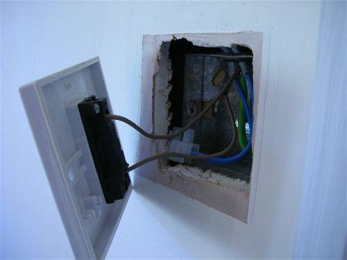
Hidden location
Models for indoor installation are made on a different principle. Since the mechanism is hidden in the thickness of the wall, and only the control keys remain outside, there is no need for a dielectric casing. In one way or another, a recess is made with a diameter of at least 70 mm and a depth of about 50 mm, in which a special installation box is fixed. The exact dimensions depend on the features of the switch and the nuances of installation. For example, if the basis is a drywall sheet, then boxes with a special type of fastening are used. After fixing, installation inside it and further connection of the light switch are carried out. The circuit is similar to the above, with the only difference being that the number of switched lines must be taken into account.
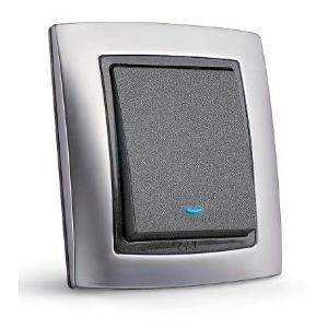
Night "alarm"
At night, when there is not enough lighting in the room, you have to literally feel the switch keys. And this is irritation and worn walls. To solve this problem, you can connect the light switch with backlight. In such devices, there is an LED that glows at a time when the lamp is de-energized by the key. Such an alarm gives a very weak glow, sufficient only to assist in finding the switch. The LED is connected via a resistor parallel to the main switching contact.
Universal switching
No less interesting is the connection of a light switch through passage. Such a device allows you to turn on / off lighting from two or more points. For example, going up to a long corridor and pressing a key, you can light up the lamps, and at the end of the path use another switch to turn off the line. Inside it there are three clamps: a phase wire is connected to one, and lines from the other two go to the corresponding contacts of another switch. Circuit disconnection is carried out in the junction box.
Driving without touch
But connecting a remote light switch makes it possible to control several light sources via radio or infrared beam. Although the schemes vary significantly, the following correspondence is most often fulfilled: A, B, C, D (yellow - white - green - blue) - these are lines to fixtures or lamps. Blue and brown - power supply 220 V. Black contact - "zero".