The collector electric motor is a synchronous electric machine in which the current switch in the winding and the rotor position sensor are made in the form of the same device - the brush-collector assembly. This device can be of different types.
Varieties
A DC collector motor usually includes elements such as:
- three-pole rotor on plain bearings;
- bipolar stator with permanent magnets;
- copper plates as brushes of the collector assembly.
This set is typical for the most low-power solutions, usually used in children's toys, where high power is not required. The structure of more powerful engines includes several more structural elements:
- four graphite brushes in the form of a collector assembly;
- a rotor with several poles on rolling bearings;
- a four-pole permanent magnet stator.
Most often, an electric motor device of this type is used in modern cars to implement a fan drive for the cooling and ventilation system, washer pumps, wipers and other elements. There are more complex units.
An electric motor power of several hundred watts involves the use of a four-pole stator made of electromagnets. To connect its windings, one of several methods can be used:
- In series with the rotor. In this case, a large maximum torque is obtained, however, due to the high idle speed, there is a high risk of engine damage.
- In parallel with the rotor. In this case, the speed remains stable under changing load conditions, however, the maximum torque is noticeably less.
- Mixed excitation, when part of the winding is connected in series, and part in parallel. In this case, the merits of the previous options are combined. This type is used for car starters.
- Independent excitation, which uses a separate power source. In this case, the characteristics corresponding to the parallel connection are obtained. This option is used quite rarely.
A collector electric motor has certain advantages: they are easy to manufacture, repair, operate, and their service life is quite large. The following are usually highlighted as disadvantages: the effective designs of such devices are usually high-speed and low-torque, so most drives require the installation of gearboxes. This statement is fully justified, since an electric machine oriented at a low speed is characterized by low efficiency, as well as the associated cooling problems. The latter are such that it is difficult for them to find an elegant solution.
Universal Brush Motor
This option is a kind of constant current collector machine, capable of operating on direct and alternating current. The device is widespread in some types of household appliances and hand tools due to its small size, light weight, low cost and ease of speed control. Quite often found as a traction machine on the railways of the United States and Europe. You can consider the device of the electric motor.
Design features
For a better understanding of this issue, you should consider in more detail what formed the basis of the presented device. The universal collector type of electric motor is a direct current device having excitation windings connected in series, optimized for operation on alternating current of a household electric power supply network. The rotation of the motor occurs in one direction, regardless of polarity. This is due to the fact that the series connection of the stator and rotor windings leads to a simultaneous change in their magnetic poles, and due to this, the resulting moment is directed in one direction.
What is it made of?
A collector AC motor involves the use of a soft magnetic material with a small hysteresis in the stator design. To reduce eddy current losses , this element is made of stacked insulated plates. As a subset of AC collector machines, it is customary to distinguish pulsating current aggregates, which are obtained by rectifying the current of a single-phase circuit without applying ripple smoothing.
The AC collector electric motor is most often characterized by this feature: in the low-speed mode, the inductive resistance of the stator windings does not allow current to be consumed beyond certain limits, while the maximum motor torque is also limited to 3-5 from the nominal. Rapprochement of mechanical characteristics is achieved through the use of stator windings sectioning - separate outputs are used to connect alternating current.
A rather difficult task involves switching a powerful AC collector machine. At the moment when the section passes neutral, the magnetic field, which is in engagement with the rotor, reverses its direction, and this causes the generation of reactive EMF in the section. This happens when operating on AC. In AC collector machines, a reactive EMF also takes place. A transformer EMF is immediately noted, since the rotor is located in the stator magnetic field pulsating in time. A soft start of the collector electric motor is impossible, since at this moment the amplitude of the machine will be maximum, and as it approaches the speed of synchronism it will be proportionally reduced. With further acceleration, a new increase will be noted. To solve the switching problem in this case, several sequential steps are proposed:
- When designing, a single-turn section should be preferred, which will reduce the clutch flow.
- The active resistance of the section needs to be increased, for which the most promising elements are resistors in the collector plates, where good cooling is observed.
- The collector must be actively sanded with brushes of maximum hardness with the highest resistance.
- Reactive EMF can be compensated by using additional poles with series windings, and parallel windings are applicable to compensate for transformer EMF. Since the value of the last parameter is a function of the angular velocity of the rotor and the magnetization current, such windings require the use of subordinate control systems, which do not yet exist.
- The frequency of the supply circuits should be as low as possible. The most popular options are 16 and 25 Hz.
- Reverse of the UKD is done by switching the polarity of the inclusion of the stator or rotor windings.
Advantages and disadvantages
For comparison, the following conditions are used: the devices are connected to a household electrical network with a voltage of 220 volts and a frequency of 50 Hz, the engine power is the same. The difference in the mechanical characteristics of the devices may be a disadvantage or an advantage, depending on the requirements for the drive.
So, the AC collector motor: advantages in comparison with a DC unit:
- Connection to the network is carried out directly, while there is no need to use additional components. In the case of a DC unit, rectification is required.
- Starting current is much less, which is very important for devices used in everyday life.
- If there is a control circuit, its device is much simpler - a rheostat and a thyristor. If the electronic component breaks down, then the collector motor, the price of which depends on power and is from 1400 rubles or more, will remain operational, but will immediately turn on at full power.
There are certain disadvantages:
- Due to the loss of magnetization reversal of the stator and inductance, the overall efficiency is markedly reduced.
- The maximum moment is also reduced.
Single-phase collector motors have certain advantages in comparison with asynchronous:
- compactness;
- lack of reference to the network frequency and speed;
- significant starting torque;
- a proportional decrease and increase in speed in automatic mode, as well as an increase in torque with increasing load, while the supply voltage remains unchanged;
- the speed control can be smooth over a fairly wide range by changing the supply voltage.
Disadvantages Compared to Asynchronous Motors
- when the load changes, the speed will be unstable;
- brush-collector unit makes the device not too reliable (the need to use the most rigid brushes significantly reduces the resource);
- AC switching causes strong sparking on the collector, while radio interference is generated;
- high noise level during operation;
- The collector is characterized by a large number of parts, which makes the engine quite massive.
A modern collector electric motor is characterized by a resource comparable to the capabilities of mechanical gears and working bodies.
Other comparisons
When comparing collector and induction motors of the same power, regardless of the rated frequency of the latter, a different characteristic is obtained. This will be described in more detail below. Universal collector motor implements a “soft” characteristic. In this case, the moment is directly proportional to the load on the shaft, while the speed is inversely proportional to it. The rated moment is usually less than the maximum by 3-5 times. The idle speed limitation is characterized solely by losses in the engine, and when a powerful unit is turned on without load, it can be destroyed.
The characteristic of the induction motor is “fan”, that is, the unit maintains a speed close to the nominal, increasing the torque as sharply as possible with a slight decrease in speed. If we are talking about a significant change in this indicator, then the engine torque not only does not increase, but also drops to zero, which leads to a complete stop. The idle speed slightly exceeds the nominal, while remaining constant. A characteristic of a single-phase induction motor is an additional set of problems associated with starting, since it does not develop a starting torque under normal conditions. The magnetic field of a single-phase stator, pulsating in time, splits into two fields with opposite phases, which makes starting without all kinds of tricks impossible:
- capacity creating an artificial phase;
- split groove;
- active resistance, forming an artificial phase.
Theoretically, a field rotating in antiphase reduces the maximum efficiency of a single-phase asynchronous unit to 50-60% due to losses in a supersaturated magnetic system and windings loaded with antipole currents. It turns out that there are two electric machines on one shaft, while one works in motor mode, and the second - in the opposition mode. It turns out that electric motors single-phase collector do not know competitors in the corresponding networks. What deserved such a high popularity.
The mechanical characteristics of the electric motor provides it with a certain scope of use. Small revolutions, limited by the frequency of the AC network, make asynchronous units of similar power large in weight and size in comparison with universal collector ones. However, when you turn on the inverter with a high frequency, a comparable size and weight can be achieved. There remains the rigidity of the mechanical characteristics of the electric motor, to which the losses due to current conversion are added, as well as an increase in the frequency, and magnetic and inductive losses increase.
Analogs without collector unit
The AC collector electric motor has an analogue that is closest to it in terms of mechanical characteristic, a valve, where the brush-collector assembly was replaced with an inverter equipped with a rotor position sensor. The following system is used as an electronic analogue of this unit: a rectifier, a synchronous motor with a rotor angular position sensor, combined with an inverter. However, the presence of permanent magnets in the rotor leads to a decrease in the maximum moment while maintaining the dimensions.
Operating principle
The collector electric motor device demonstrates how the device converts electrical energy into mechanical and vice versa. This suggests its potential use as a generator. It is worthwhile to consider in more detail the collector electric motor, the circuit of which will demonstrate its capabilities.
The laws of physics clearly indicate that when an electric current is passed through a conductor located in a magnetic field, an effect of a certain force appears on it. In this case, the rule of the right hand works, which has a direct effect on the power of the electric motor. The collector motor works precisely on this basic principle.
Physics teaches us that small rules are the basis for creating the right things. This served as the basis for creating a frame rotating in a magnetic field, which allowed us to create a collector electric motor. The diagram shows that a pair of conductors is placed in a magnetic field, the current of which is directed in opposite directions, and hence the forces too. Their sum gives the necessary torque. The device of the electric motor is much more complicated, since a whole complex of necessary elements is added to it, in particular, a collector that provides the same direction of current over the poles. The unevenness of the course was eliminated by placing several more coils at the anchor, while the permanent magnets were replaced by coils, which allowed us to avoid the need to use direct current. This made it possible to give the torque a single direction.
DIY electric motor repair
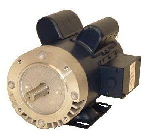
Like any other device, this unit can fail for any reason. If the electric motor, the photo of which you can see in our review, cannot gain the required number of revolutions, or the shaft does not spin when it is started, it is necessary to check if its fuses are blown, if there are any openings in the electric circuit of the armature, or if the device itself is overloaded. Very often, overload leads to the consumption of amperage of an abnormal value. To eliminate this malfunction, it is necessary to carefully inspect the mechanical transmission and brake, and then eliminate the causes of overloads.
The device of the electric motor is such that at startup it consumes a certain amount of current. If it is greater than the nominal value, it is required to check the consistency of connecting the parallel and serial windings relative to each other, as well as with respect to the rheostat. When repairing electric motors with their own hands, most often quite specific errors are made. In particular, the shunt winding can be connected in series with the electrical resistance of the rheostat, or connected to one pole of the electrical network.
The consistency of connecting the working field winding is checked by connecting one of the ends of the shunt winding with the anchor end, and the second with an electric conductor coming from the rheostat arc. Typically, the cross section of this electrical conductor is slightly smaller than the others, so it can be detected without a megohmmeter. After turning on the power switch and shifting the slider of the rheostat to the middle position, power is supplied to the free ends. By means of a control lamp, a sequential check of all conductive ends is carried out. When touching one of them, the lamp should light up, but with the other it should not. So the whole electric motor is tested. The price of the work will depend on the type of breakdown of the unit.
If during the operation of the device there is a number of revolutions that is less than the nominal one, then the main reasons for this are usually the following: low mains voltage, overload of the device, high exciting current.If reverse inoperability is noted, it is necessary to check the excitation circuit, eliminate all detected defects, after which you can set the normal value of the excitation current. In some cases, it may be necessary to rewind the motors.
When the cause of the unit's inoperability is the erroneous coupling of the parallel and serial field windings, it is necessary to restore the correct connection order. If it is not possible to rectify such a malfunction in a simple way, it may be necessary to rewind the motors. It is also necessary to check the magnitude of the voltage in the electric network, since with an increase in its nominal indicator, the revolutions of the device can increase.