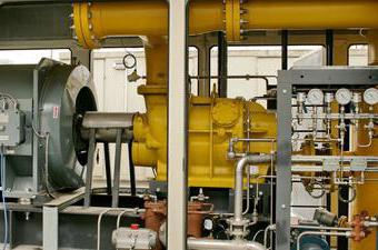
An individual heating unit is a whole complex of devices located in a separate room, which includes elements of thermal equipment. It provides the connection to the heat network of these units, their transformation, management of heat consumption modes, operability, distribution by types of coolant consumption and regulation of its parameters.
Individual heating item
A thermal installation engaged in servicing a building or its individual parts is an individual heating unit, or ITP for short. It is designed to provide hot water supply, ventilation and heat to residential buildings, housing and communal services, as well as industrial complexes.
For its functioning, it will be necessary to connect to the system water and heat, as well as the power supply necessary to activate the circulation pumping equipment.
An individual small heat center can be used in a single-family house or in a small building connected directly to a centralized heat supply network. Such equipment is designed for space heating and water heating.
A large individual heating center serves the maintenance of large or multi-apartment buildings. Its power ranges from 50 kW to 2 MW.
Main goals
An individual heat point provides the following tasks:
- Accounting for heat and coolant.
- Protection of the heat supply system from an emergency increase in the parameters of the coolant.
- Turn off the heat system.
- Uniform distribution of the heat carrier in the heat consumption system.
- Adjustment and control of circulating fluid parameters.
- Conversion of the type of coolant.
Benefits
- High profitability.
- Long-term operation of an individual heating unit has shown that modern equipment of this type, unlike other non-automated processes, consumes 30% less thermal energy.
- Operating costs are reduced by about 40-60%.
- Choosing the optimal heat consumption mode and fine-tuning will reduce heat loss by up to 15%.
- Silent work.
- Compactness.
- The overall dimensions of modern heating units are directly related to the heat load. With compact placement, an individual heating unit with a load of up to 2 Gcal / hour occupies an area of 25-30 m 2 .
- The possibility of location of this device in the basement of small-sized rooms (both in existing and in newly built buildings).
- The process is fully automated.
- Maintenance of this heating equipment does not require highly qualified personnel.
- ITP (individual heat point) provides comfort in the room and guarantees effective energy saving.
- The ability to set the mode, focusing on the time of day, the application of the weekend and holiday, as well as weather compensation.
- Individual production depending on customer requirements.
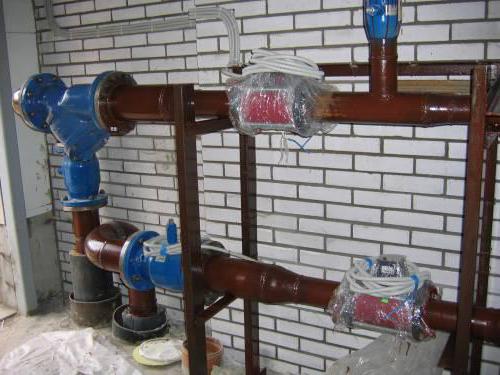
Heat metering
The basis of energy-saving measures is a metering device. This accounting is required to perform calculations for the amount of heat consumed between the heat supply company and the subscriber. Indeed, very often the estimated consumption is much higher than the actual one due to the fact that when calculating the load, the suppliers of thermal energy overestimate their values, referring to additional costs. Such situations will be avoided by the installation of metering devices.
Purpose of metering devices
- Ensuring fair financial settlements between consumers and suppliers of energy resources.
- Documentation of the parameters of the heat supply system, such as pressure, temperature and flow rate.
- Monitoring the rational use of the power system.
- Monitoring the hydraulic and thermal operation of the heat consumption and heat supply systems.
Classic meter design
- Thermal energy meter.
- Pressure gauge.
- Thermometer.
- Thermal converter in return and supply piping.
- Primary flow transmitter.
- The mesh magnetic filter.
Service
- Connecting a reading device and subsequent reading.
- Analysis of errors and clarification of the causes of their occurrence.
- Check the integrity of the seals.
- Analysis of the results.
- Checking technological indicators, as well as comparing the readings of thermometers on the supply and return pipelines.
- Topping up the oil in the sleeves, cleaning the filters, checking the grounding contacts.
- Removing dirt and dust.
- Recommendations for the proper operation of internal heat supply networks.
Scheme of the heat point
The following nodes are included in the classical ITP scheme:
- Entering a heat network.
- Metering device.
- Connection of a ventilation system.
- Heating system connection.
- Hot water connection.
- Pressure balancing between heat and heat supply systems.
- Make-up of heating and ventilation systems connected in an independent manner.
When developing a design for a heating unit, the mandatory units are:
- Metering device.
- Pressure matching.
- Entering a heat network.
Complete set with other nodes, as well as their number, is selected depending on the design solution.
Consumption systems
The standard scheme of an individual heating unit may have the following systems for providing thermal energy to consumers:
- Heating.
- Hot water supply.
- Heating and hot water supply.
- Heating, hot water and ventilation.
ITP for heating
ITP (individual heat point) - an independent circuit with the installation of a plate heat exchanger, which is designed for 100% load. A dual pump is provided to compensate for pressure loss. Make-up of the heating system is provided from the return pipe of the heating networks.
This heat point can be additionally equipped with a hot water supply unit, metering device, as well as other necessary blocks and units.
ITP for domestic hot water
ITP (individual heat point) - an independent, parallel and single-stage scheme. The package includes two plate-type heat exchangers, the operation of each of them is designed for 50% of the load. There is also a group of pumps designed to compensate for the decrease in pressure.
Additionally, the heating center can be equipped with a heating system unit, metering device and other necessary units and units.
ITP for heating and hot water
In this case, the work of an individual heating unit (ITP) is organized according to an independent scheme. For the heating system, a plate heat exchanger is provided, which is designed for a 100% load. The hot water supply scheme is independent, two-stage, with two plate-type heat exchangers. In order to compensate for the decrease in pressure level, a group of pumps is provided.
The heating system is recharged using the appropriate pumping equipment from the return pipe of the heating networks. Hot water is supplied from the cold water system.
In addition, the ITP (individual heat point) is equipped with a metering device.
ITP for heating, hot water and ventilation
Connection of the thermal installation is carried out according to an independent scheme. For the heating and ventilation system, a plate heat exchanger is used, designed for a 100% load. The hot water supply scheme is independent, parallel, single-stage, with two plate heat exchangers rated for 50% of the load each. Compensation for lowering the pressure level is carried out through a group of pumps.
The heating system is fed from the return pipe of the heating networks. Hot water is supplied from the cold water system.
Additionally, an individual heating unit in an apartment building can be equipped with a metering device.
Principle of operation
The scheme of the heating station directly depends on the characteristics of the source supplying energy to the ITP, as well as on the characteristics of the consumers it serves. The most common for this thermal installation is a closed hot water system with an independent heating system.
An individual heating unit, the principle of operation is as follows:
- Through the supply pipe, the coolant enters the ITP, transfers heat to the heaters of the heating system and hot water supply, and also enters the ventilation system.
- Then the coolant is sent to the return pipe and fed back through the main network for reuse to the heat generating enterprise.
- A certain amount of coolant can be consumed by consumers. In order to make up for losses at the heat source, thermal power plants and boiler houses are provided with recharge systems that use water treatment systems of these enterprises as a heat source.
- The tap water entering the thermal installation flows through the pumping equipment of the cold water supply system. Then some of its volume is delivered to consumers, another is heated in the first stage hot water heater, then it is sent to the hot water circulation circuit.
- The water in the circulation circuit through the circulation pumping equipment for hot water supply moves in a circle from the heating station to consumers and vice versa. In this case, as necessary, consumers select water from the circuit.
- During the circulation of the fluid along the circuit, it gradually gives off its own heat. To maintain the optimum temperature of the coolant, it is regularly heated in the second stage of the hot water heater.
- The heating system is also a closed loop, along which the coolant moves with the help of circulation pumps from the heat point to consumers and vice versa.
- During operation, coolant leaks from the heating system circuit may occur. Replenishment of losses is carried out by the ITP recharge system, which uses primary heating networks as a heat source.
Admission to operation
In order to prepare an individual heating unit in the house for admission to operation, it is necessary to submit the following list of documents to Energy Supervision:
- The current technical conditions for connection and a certificate of their implementation from the energy supply organization.
- Design documentation with all necessary approvals.
- Act of responsibility of the parties for the operation and separation of the balance sheet, drawn up by the consumer and representatives of the energy supply organization.
- Act of readiness for permanent or temporary operation of a subscriber branch of a heat point.
- ITP passport with a brief description of heat supply systems.
- Help on the readiness of the meter for thermal energy.
- Certificate of conclusion of a contract with a heat supplying organization.
- Act on acceptance of work performed (indicating the license number and date of issue) between the consumer and the installation organization.
- The order on the appointment of the person responsible for the safe operation and good condition of thermal installations and heating networks.
- List of operational and operational-repairing persons responsible for servicing heating networks and heating plants.
- A copy of the welder’s certificate.
- Certificates for used electrodes and pipelines.
- Acts on hidden work, the executive scheme of the heat point indicating the numbering of valves, as well as piping and valves.
- Act on flushing and pressure testing of systems (heating networks, heating system and hot water supply system).
- Job descriptions, fire safety and safety instructions .
- Operating Instructions.
- The certificate of admission to the operation of networks and installations.
- Log book of instrumentation, issuance of work orders, tolerances, operational, accounting of defects detected during inspection of installations and networks, knowledge testing, as well as briefings.
- Outfit from heating networks for connection.
Safety Precautions and Operation
The personnel servicing the heating station must have the appropriate qualifications, and responsible persons should be familiarized with the operating rules that are stipulated in the technical documentation. This is a mandatory principle of an individual heat point approved for operation.
It is forbidden to start pumping equipment with shut-off valves at the inlet and in the absence of water in the system.
During operation it is necessary:
- Monitor pressure readings on pressure gauges installed on the supply and return pipes.
- Observe the absence of extraneous noise, and also prevent excessive vibration.
- Monitor the heating of the electric motor.
Excessive force is not allowed in the case of manual control of the valve, and in the presence of pressure in the system, the regulators must not be disassembled.
Before starting a heat point, it is necessary to flush the heat consumption system and pipelines.