Before installing the water supply system, you need to draw up a detailed wiring diagram, focusing on how the water will be supplied - centrally or autonomously, and what is the number of water intake points - dishwasher and washing machine, hot water column, kitchen faucet, sink, shower, toilet, bath. In addition, it is necessary to calculate the approximate consumption of water, taking into account the number of people living in the house, as well as watering the garden and orchard. And find out what the pumping station should be , the scheme for connecting it to the water supply network. You can learn about all this in this article.
What is a pumping station?
When installing an autonomous water supply system and connecting the water supply to communal trunk networks, the consumer dreams of regular water pressure in the system. Thus, for lifting from a well located on a personal plot or well, special pumping equipment can be used. It comes in various capacities and models; it can be located in various parts of the water supply system. Surface devices are placed at ground level; submersible devices are lowered directly into a well or well.
Essential elements
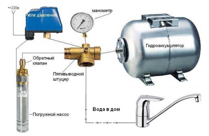
Pumping equipment should not constantly work, as continuous operation can lead to rapid wear of the mechanisms and components of this device. However, at the same time you want to use water at any time. There is a way out - a pump station is going to (the connection diagram and the main parts are presented below), which provides a constant pressure in the water supply system. So, we will consider the main components of the pumping station.
Pump
Very often, the pumping station is equipped with surface pumps. They, through the inlet pipe with a filter, pump water from the main network, borehole or well.
Battery
A hydraulic accumulator (or pressure accumulator) is a design of certain overall dimensions, inside of which there is an internal container or an elastic partition made of rubber. When the pressure in the system increases, the partition or capacity stretches, respectively, when it decreases, it decreases, directing water into the system and maintaining constant pressure indicators.
Control node
This element determines at what moment it is necessary to start the pumping device, and when its operation is not required. The on and off parameters are determined by the pressure parameters in the system, measured by a manometer.
Installation options
Regardless of the location of the water source, the installation of the pumping station can be carried out in three main places - in the basement, a separate building and a caisson. Let's consider them in more detail.
Basement
Such a pump station installation greatly facilitates equipment maintenance, since in this case free access to the mechanisms for their repair and maintenance is provided. However, pumping devices are quite a noisy thing, so when choosing this option, you should think about noise insulation measures.
Detached building
In this case, the connection diagram of the pumping station to the well is provided in a separate building, which is located above the wellhead or well. Despite the obvious benefit of this option, the construction of a stand-alone structure for technical structures is a rather costly process.
Caisson
A caisson is a design that looks like a container whose bottom is below the freezing level. Perhaps the construction of large caissons, in which it is allowed to place pumping equipment.
Pumping station: reviews
According to consumer reviews of the pumping equipment used in the stations, in most cases it is not satisfactory. If you want to play it safe, then it is advisable to purchase stations with equipment from well-known European companies.
Placement Selection
Before choosing where the pumping station will be located (the connection diagram also depends on the location), you need to know the requirements for its installation.
- To avoid increased vibration, the pump station must be installed on a solid base. Lack of reliable fastening and a solid base can lead to the formation of backlash at the joints of pipelines that will cause leaks. But at the same time, pumping equipment should not come into contact with the ceiling and walls.
- The pump station (the connection diagram is presented below) must be installed either in a heated room, or it must be qualitatively isolated from the effects of negative temperatures. Otherwise, lowering the temperature can damage almost all components.
If you plan to use the station year-round, you will need to make quite complicated preparatory work. Automatic pumping stations (wiring diagrams also need to be thought out in advance) must be installed in warm rooms, and the pipeline from the house to the well must be laid below the freezing level or insulated.
Organization of the water supply system
In this case, an ideal option is an autonomous water supply system, which is easy to build. And the cost of such a system is quite democratic. Therefore, it remains to find out what a pumping station should be for a private house, the scheme for connecting it to the water supply system.
There are two main schemes for organizing an autonomous water supply system: based on a well and based on a well. The autonomous network device in the latter case begins with the drilling of a well. It is advisable if the project for the well, the layout of communications and the installation of the pumping station will be carried out in conjunction with the design of the main building and courtyards. In this case, it is possible to design the installation of part of the equipment on the basement adjacent to the building of buildings or in the basement so that the well and pump station (expert reviews confirm this) are in harmony with the overall architectural style of the estate. And most importantly, this option in winter does not require additional protection of communications and equipment from freezing. Equipment arranged in one place will be convenient for repair and maintenance.
Pumping stations for the home: wiring diagram
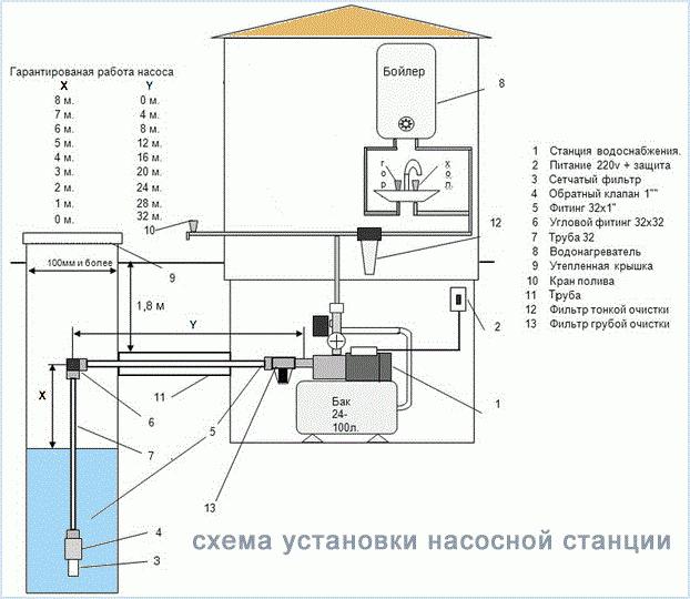
Depending on the configuration of the water supply system, you can choose to connect the station to a single-pipe or two-pipe system. The latter option is used to increase the depth with which pumping stations for the house (the connection diagram is discussed below) will be able to receive water.
If the well depth is not more than 10 meters, then in this case a one-pipe scheme is used. With a suction depth of more than 20 meters, it is more advisable to use a two-pipe scheme with an ejector.
Double pipe circuit
Connection of the pumping station to the well: two-pipe scheme.
- At the first stage, it is necessary to assemble an ejector, which is a separate unit made of cast iron with three exits for connecting the pipeline.
- A filter mesh is installed in the lower part of the ejector, which, when sand or other small particles get from a well or a well, protects pumping equipment from failure.
- Then, a plastic bell is installed in the upper part of the ejector; a 32 mm cross-section is connected to it. To get to the cross section of the water pipe, you may have to mount several runs at the same time.
- At the end of the drive, a coupling is installed that provides a transition to a polyethylene pipeline. As a rule, this coupling is made of bronze.
- Next, a head is installed on the casing of the well.
- After this, the required depth of the pipeline is determined. To do this, a long object is lowered into the drilled well . As a result, the location level of the inlet pipe should be about one meter from the bottom of the well to prevent stones or sand from falling from the bottom.
- A pipeline made of polyethylene is connected to the ejector unit, the length of which must be equal to the sum of the distance from the depth of the well and the pump to the wellhead (minus 1 meter).
- Then, a knee with a 90 ° rotation is mounted on the head of the well.
- Plastic pipelines are pushed through the straight elbow, which lead to the ejector unit (at the end, the space between the pipelines and the inside of the elbow can be filled with foam).
- The ejector device lowers to the desired depth. The correctness of the depth can be verified by the mark that was previously made on the pipeline.
- At the top of the casing , a home-made head is fixed, consisting of a knee rotated at an angle of 90 °. The head is fixed on the casing of the well by means of specialized reinforced adhesive tape for plumbing.
Connection to the internal water supply
Pumping station for a private house: a scheme for connecting to an internal water supply system.
- An HDPE pipe from external networks (from a well or a well) enters the building and ends with a brass fitting with a transition to a threaded connection with a diameter of 32 mm.
- Compounds located before the fine filter have a diameter of 25 mm. A tee with a drain tap is connected to the brass fitting (when replacing or repairing water supply elements). Next, you need to turn towards the station. This will require a 90 degree connection angle.
- After the corner, a quick-disconnect connection with a ball valve is established. Next, a dirt collector (strainer ) is installed to protect it from sand, small stones, etc.
- If a connection diagram of the pumping station to the well is provided, then the filter should be installed in the well in front of the relief valve. In the case of pumping equipment, a brass manifold for the pressure gauge, damper tank and pressure switch leaves the well. For the first option, a collector is not required because the pumping station for water supply at home is equipped with a tank and a pressure switch. If a pump is provided from the well, the pressure switch is mounted in the collector in a horizontal position from above, the damper tank is connected from below, the fine filter is connected to the remaining connection.
- After the filter, a transition to a polypropylene pipeline with a diameter of 25 mm is established. Fiber-reinforced products are used for hot water, unreinforced for cold water. Pipelines are joined end-to-end after hot softening (soldering) using a special soldering iron.
- Then a cold water collector is installed, and shut-off devices are mounted on the pipelines in case of repair.
Connection with storage tank
The connection diagram of the pumping station with the storage tank is used when the volume of water is insignificant or the debit of the well (well) is small. A storage tank is installed between the water source and the end user. The volume of the tank, depending on the daily intake, can be from 300 to 1000 liters. In urban conditions, the daily volume of water per person is taken from the flow rate of 170-250 liters, in the absence of a bath and in summer conditions - 50-75 liters.
The connection diagram of a pump station with a storage tank has the following advantages:
- In winter, the storage tank does not require additional heating.
- The storage tank does not take up space in the house.
- It is allowed to use large tanks.
For underground installation, it is necessary to use storage tanks of a round or ribbed shape, which will ensure high-quality connection of the pumping station to the well. The connection diagram using the storage tank is a cascade of separately controlled pumps.