Almost any electric motor can be made to rotate in one or the other direction. This is often necessary, especially when designing various mechanisms, for example, systems for closing and opening gates. Typically, the factory direction of the shaft, which is considered direct, is indicated on the motor housing. Torsion in the other direction in this case will be reversible.
What is reverse
Simply put, reverse is a change in the direction of movement of a mechanism in the opposite direction from the selected main one. The reverse circuit can be obtained in several ways:
In the first case, by switching gear links connecting the drive shaft to the driven shaft, the latter is rotated in the opposite direction. By this principle, all gearboxes work.
The electrical method involves a direct effect on the engine itself, where electromagnetic forces take part in changing the movement of the rotor. This method benefits by not requiring the use of complex mechanical transformations.
In order to get an electric motor reverse, it is necessary to assemble a special electric circuit, which is called a motor reverse circuit. It will be different for different types of electric machines and supply voltage.
Where reverse is applied
It is easier to list cases where reverse is not used. Almost all mechanics are built on the transmission of torque clockwise and vice versa. This may include:
- Household appliances: washing machines, audio players.
- Power tools: reversible drills, screwdrivers, wrenches.
- Machine tools: boring, turning, milling.
- Vehicles.
- Special equipment: crane equipment, winches.
- Elements of automation.
- Robotics
The situation that an ordinary person most often encounters in practice is the need to assemble a circuit for connecting the reverse of an asynchronous alternating current electric motor or a DC collector motor.
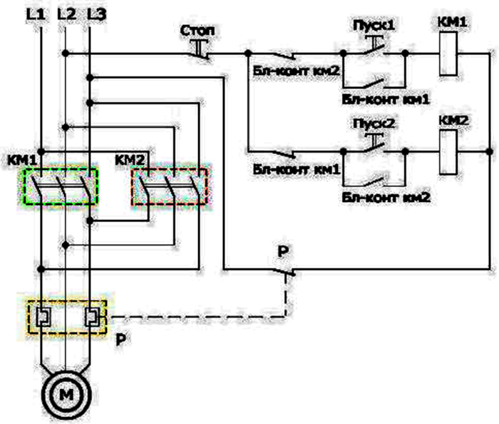
Connection of an 380 V asynchronous motor to a three-phase network in reverse
The asynchronous connection diagram in the forward direction has a certain sequence of supplying phases A, B, C to the motor contacts. It is possible to modify it, for example, by adding a switch that would swap any two phases. In this way, you can get a reverse circuit of the electric motor. In practical schemes, such phases are considered to be B and A.
Optional equipment:
- Magnetic starters (KM1 and KM2).
- Three-button station, where two contacts have a normally open position (in the initial state, the contact does not conduct current, pressing the button causes a circuit to close), one normally closed.
The scheme works as follows:
- By switching on the automatic fuses AB1 (power line), AB2 (control circuit), the current flows to the three-button switch and the terminals of the magnetic contactors, which are open in the initial state.
- By pressing the “Forward” button, the current flows to the coil of the electromagnet of the contactor 1, which attracts the armature with power contacts. At the same time, the control circuit of contactor 2 is interrupted, it is now impossible to turn it on with the “Reverse” button.
- The motor shaft begins to rotate in the main direction.
- By pressing the “Stop” button, the current in the control winding circuit is interrupted, the electromagnet releases the armature, the power contacts open, the lock contact of the “Reverse” button closes, and now it can be pressed.
- When the “Reverse” button is pressed, similar processes occur only in the contactor 2 circuit. The motor shaft will rotate in the opposite direction from the main direction.
Connecting a 220V motor to a single-phase network in reverse
In this case, it is possible to achieve a reverse movement of the motor shaft if there is access to the conclusions of its starting and working windings. These motors have 4 outputs: two to the starting winding connected with a capacitor, two to the working one.
If there is no information on the purpose of the windings, it can be obtained by the method of dialing. The resistance of the starting winding will always be greater than the working one due to the smaller cross section of the wire with which it is wound.
In a simplified version, the 220 V motor connection diagrams are fed to the working winding, one end of the starting winding per phase or network zero (no difference). The engine will begin to rotate in a certain direction. To obtain a reverse circuit, you need to disconnect the end of the starting winding from the contact and connect the other end of the same winding there.
To get a full working circuit of the inclusion, you need the equipment:
- Protective circuit breaker.
- Button post.
- Electromagnetic contactors.
The reverse and forward running circuit in this case is very similar to the three-phase motor connection diagram, but switching here does not occur in phases, but in the starting winding in one or the other direction.
Reverse circuit of a three-phase motor in a single-phase network
Since the three-phase asynchronous motor will lack two phases, they must be compensated by capacitors - starting and working, on which both windings are switched. From where to attach the third, the torsion of the shaft in one direction or another depends.
The diagram below shows that the winding at number 3 through a working capacitor is connected to a three-position toggle switch, which is responsible for the operation of the motor forward / backward. Its two other contacts are combined with windings 2 and 1.
When you turn on the engine, you must adhere to the following algorithm of actions:
- Apply power to the circuit through a plug or circuit breaker.
- Toggle switch to switch operating modes to the forward or backward position (reverse).
- Set the power toggle switch to the ON position.
- Press the “Start” button for a time not exceeding three seconds to start the engine.
Wiring diagram for DC reverse motor
DC motors are a bit more difficult to connect than electric cars with variable networks. The difficulty lies in the fact that the design of such devices can be different, or rather different is the way the excitation of the winding. On this basis, the engines are distinguished:
- An independent method of arousal.
- Excitations of an independent (there are serial, parallel and mixed connections).
Regarding the first type of devices, here the anchor is not connected to the stator winding, they are powered by each from its source. This achieves the huge power of the engines used in production.
In machine tools and fans, parallel excitation motors are used, where the source energy is the same for all windings. Electric vehicles are built on the basis of sequential excitation of the windings. Mixed arousal is less common.
In all the described types of engine designs, it is possible to start the rotor in the opposite direction from the main stroke, that is, reverse:
- With a sequential excitation scheme, it does not matter where to change the direction of the current in the armature or stator - in both cases the motor will work stably.
- In other versions of the excitation of machines, it is recommended to use only the armature winding for reversal purposes. This is due to the danger of breakage in the stator, a jump in the electromotive force (EMF) and, as a result, insulation damage.
Star-delta starter motor
With the direct start of powerful three-phase electric motors, applying a reverse control circuit, voltage drops in the network. This is due to large inrush currents flowing at this moment. To reduce the current value, a gradual start of the motor according to the star-delta scheme is used.
The bottom line is that the beginning and end of each stator winding is displayed in a terminal box. The circuit is controlled by three contactors. They gradually include the windings in the star, and then, when the engine is accelerating, they bring the system to working condition when connected by a triangle.
How to distinguish a reversing starter from a direct
Reverse starter is a more complex device. In fact, it consists of two ordinary direct starters, the latter combined in one housing. The internal circuitry of the reversing device is characterized by the fact that it is impossible to start two modes simultaneously - direct and reverse. The blocking circuit, which can be electrical or mechanical, is responsible for this process.
Finally
It must be remembered that it is allowed to connect three-phase voltage motors to a 380V network only by qualified specialists who are authorized to work with high-voltage equipment. Handicraft circuits can cause electrical injuries!