Transformers play a significant role in electrical engineering, performing the functions of conversion, insulation, measurement and protection. One of the most common tasks of devices of this type is the regulation of individual current parameters. In particular, voltage transformers (VT) convert the primary power indicators to optimal values, from the point of view of consumers.
General equipment design
The technical basis of the transformer is formed by the electromagnetic filling, which ensures the functional processes of the device. The size of the equipment may vary depending on the requirements for the power load in the circuit. In a typical design, the transformer has current input and output devices, and the main working elements perform voltage conversion tasks. A set of insulators, fuses and a relay protection device is responsible for ensuring the reliability and safety of technological processes. The design of a modern low-voltage transformer also provides sensors for recording individual operating parameters, the indicators of which are sent to the control panel and become the basis for teams to regulatory bodies. The functioning of electrical components in itself requires energy supply, therefore, in some modifications, the converters are supplemented by autonomous power sources - generators, batteries or batteries.
Transformer cores
The key working elements of the VT are the so-called cores (magnetic cores) and windings. The first are of two types - rod and armor. For most low-frequency transformers up to 50 Hz, core cores are used. In the manufacture of the magnetic circuit, special metals are used, the characteristics of which depend on the working properties of the structure, for example, performance and the value of the open circuit current. The core of the voltage transformer is formed by thin sheets of alloy, insulated with each other by layers of varnish and oxide. The degree of influence of the eddy currents of the magnetic circuit will depend on the quality of this insulation. There is also a special kind of stacked cores that form structures of arbitrary section, but close to square shape. This configuration allows you to create universal magnetic cores, but they also have weaknesses. So, there is a need for tight tightening of metal plastics, since the smallest gaps reduce the coefficient of filling the working area of the coil.
Windings of voltage transformers
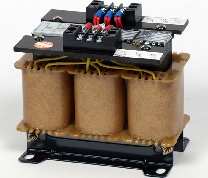
Usually two windings are used - primary and secondary. They are isolated from each other and from the core. The first level of the winding is characterized by a large number of turns made by a thin wire. This allows it to serve high voltage networks (up to 6000-10 000 V), required for basic conversion needs. The secondary winding is designed for the parallel supply of measuring instruments, relay devices and other auxiliary electrical equipment. When connecting the windings of voltage transformers, it is important to consider the markings on the output terminals. For example, power direction switches, multimeters, ammeters, wattmeters, and various meters are connected to the coils through the beginning of the primary winding (designation A), the end line (X), the beginning of the secondary winding (a) and its end (x). An additional winding with special prefixes in the designation can also be used.
Mounting hardware and grounding equipment
The list of additional elements and functional devices may be different depending on the type and characteristics of the transformer. For example, oil structures with a primary voltage index of up to 10 kV and more are provided with fittings for filling, draining and sampling technical lubricants. For oil, a tank is also provided with nozzles and regulators that control the smooth flow of fluid into the target zones. Typical valve kits most often include brackets with bolts, branch pipes, relay components, gaskets made of electric cardboard, flange elements, etc. With regard to grounding, transformers with primary voltage up to 660 V are provided with clamps with threaded fastening of bolts, studs and screws size M6. If the voltage indicator is above 660 V, then the grounding armature will have to have metal hardware connections of a format not less than M8.
The principle of operation of VT
The main functions and processes of electromagnetic induction are performed by a complex including a metal core with a set of transformer plates, primary and secondary windings. The quality of the device will depend on the accuracy of the basic calculation of the amplitude and angle of the passage of current. For the conversion in an electromagnetic field, mutual induction between several windings is responsible. The alternating current in a voltage transformer at 220 V is constantly changing, passing through a single winding. According to Faraday’s law, an electromotive force is induced once per second. In a system with a closed winding, a current will flow through the circuit by default and close to the metal core. The lower the load on the secondary winding of the transformer, the closer the actual conversion coefficient to the nominal value. The work with connecting the secondary winding to the measuring devices will especially depend on the degree of conversion, since the smallest fluctuations in the load will affect the accuracy of the measurements introduced into the instrument circuit.
Varieties of Transformers
To date, the following varieties of VT are most common:
- A cascade transformer is a device in which the primary winding is divided into several consecutive sections, and equalizing and connecting windings are responsible for the transfer of power between them.
- Grounding VT - single-phase structures in which one end of the primary winding is grounded tightly. It can also be three-phase voltage transformers with a grounded neutral from the primary winding.
- Non-earthed VT - a device with full insulation of windings with adjacent fittings.
- Double winding transformers - transformers with one secondary winding.
- Three-winding VT - transformers, in which, in addition to the primary winding, there are also primary and secondary secondary windings.
- Capacitive VT - designs characterized by the presence of capacitive dividers.
Features of electronic VT
In terms of basic metrological indicators, this type of transformer is slightly different from electrical devices. This is due to the fact that in both cases the traditional conversion channel is used. The main features of electronic transformers are the absence of high-voltage isolation, which ultimately contributes to a higher technical and economic effect from the operation of the equipment. In high-voltage networks with a primary voltage of a voltage transformer up to 660 V, the converter is connected to the central network in a galvanic manner. Information about the measured current is transmitted at high potential, as it happens in an analog-to-digital converter with an optical output. However, the dimensions and weight of electronic models are so small that they make it possible to install transformer units in the infrastructure of high-voltage wire buses even without connecting additional insulators and mounting hardware.
Transformer Characteristics
The main technical operational value is the voltage potential. On the primary winding, it can reach 100 kV, but this mainly concerns large-sized industrial stations containing several converting modules. As a rule, no more than 10 kV is supported on the primary winding. The voltage transformer for single-phase networks with a grounded neutral and does work at 100 V. As for the secondary winding, its rated voltage is 24-45 V on average. Again, energy-consuming metering devices are serviced on these circuits, for which a high power load is not required. However, secondary windings sometimes also have high potentials of more than 100 V in three-phase networks. It is also important to consider the accuracy class in evaluating the characteristics of a transformer - these are values from 0.1 to 3, which determine the degree of deviation in the conversion of the target electrical parameters.
Ferroresonant effect
Electromagnetic devices are often subjected to various kinds of negative influences and damage associated with violations in isolation. One of the most common processes of winding failure is ferroresonance perturbation. It leads to mechanical damage and overheating of the windings. The main reason for this phenomenon is called the nonlinearity of the inductance, which occurs in situations of unstable reaction of the magnetic circuit to the surrounding magnetic field. External measures can protect the voltage transformer from ferroresonance effects, including the inclusion of additional capacitors and resistors to the switched device. In electronic systems, minimizing the likelihood of induction nonlinearity also allows the programming of shutdown sequences.
Equipment application
The operation of transformer devices that convert voltage is regulated by the rules for the use of electrical engineering. Given the optimal operating values, specialists introduce substations into the infrastructure supplying the target facility. The main functions of the systems allow serving buildings and enterprises with powerful power plants, and the secondary voltage of the transformer up to 100 V controls the load for less demanding consumers like meters and metrological devices. Depending on the technical and construction parameters, VT can be used in industry, in the construction industry and in the household. In each case, transformers provide control of electrical power supply by adjusting the input power indicators in accordance with the nominal requirements of a particular facility.
Conclusion
Electromagnetic transformers provide a rather old, but still in demand principle of power regulation in electric circuits. Obsolescence of this equipment is associated with both the structural design of the equipment and functionality. Nevertheless, this does not prevent the use of current and voltage transformers for critical tasks of power supply management in large enterprises. Moreover, it cannot be said that converters of this type are not at all improved. Although the basic principles of work and even the technical implementation as a whole remain the same, engineers have recently been actively working on protection and control systems. As a result, this affects the safety, reliability and accuracy of transformers.