Signal strength indicators are used to visually assess a changing parameter at intermediate points in the device circuit. According to their testimony, one can judge the operation of individual functional modules. The use of indicators in sound signal amplifiers allows you to set a level sufficient for comfortable listening to musical compositions, while preventing the amplifier from operating outside of the range acceptable for it.
The main types of indicators
Indicators are an integral part of sound amplification devices. They allow you to get a visual assessment of the composition in the range of sound frequencies. To monitor the signal level, both arrow gauges and devices made in the form of LED columns are used, changing their geometric dimensions as the sound signal rises or falls in the selected frequency range. The main types of indicators can be distinguished:
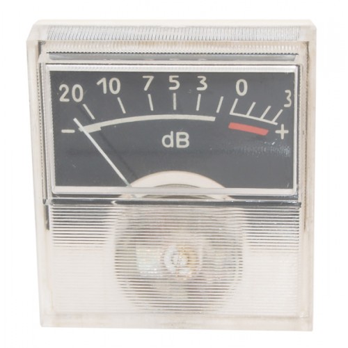
- Scale, representing devices of varying degrees of complexity, in which arrow microammeters are used to assess the strength of the sound signal.
- Peak (LED) signal level indicators that can use both single elements and LED strips.
- Peak Luminescent.
Modern sound information reproduction systems use electronic devices that reflect a number of necessary parameters. Their schemes use one or another of the main types of indicators listed above.
Simple scale
Indicators of this type contain an electromechanical microammeter with a current of the total deflection of the arrow up to 500 μA. The device operates when flowing along the winding of its DC coil. Therefore, a time-varying sound output signal must first be converted using a diode circuit.
By changing the resistance value of the resistor that limits the current flowing through the microammeter, it is possible to achieve a complete deflection of the arrow for the maximum sound signal level. The scale is graduated in percent of the maximum level or in decibels (dB) of its attenuation.
Bipolar Transistor Scales
Microammeters in the circuits of these devices are included in the collector circuit of the output stages of transistor current amplifiers, made according to the scheme with a common emitter (OE). The number of amplification stages is determined by the minimum level to which the scale of the dial indicator of the sound signal level should respond. The current value of the total deviation of the arrow can be set by the elements of the AC voltage divider supplied to the input of the dial indicator circuit for subsequent amplification.
The circuitry contains rectifiers of a constantly changing sound amplifier signal in direct current to create a more comfortable visual control of the volume of the listening composition. The scale is performed by digitizing the percentage of the current signal level with respect to its maximum value. For the maximum value, a volume level is selected whose non-linear distortion coefficient does not exceed the permissible value and is determined by international quality standards.
Scale on operational amplifiers
Operational amplifiers (op amps) with high input impedance introduce minimal distortion into the measurement circuit. Arrow level indicators for the amplifier allow you to visually control the minimum levels that are not available to the simplest meters and circuits with OE.
Op-amps are used as voltage / current converters or emitter repeaters. The electromechanical head of the microammeter has a scale reflecting (as in previous cases) the attenuation in decibels of the level of the measured signal relative to its maximum value.
Peak Indicators
LED indicators of this type are based on voltage comparators of the input signal level. The voltage at their outputs appears when the input signal exceeds a certain predetermined value by the circuit elements of the value of the input signal. At the same time, the voltage level that arises at the output of the comparator is enough to light up the LED of the indicator line.
The more threshold devices the signal level indicator circuitry contains, the less noticeable will be the stepwise movement of the LED column on the scale, the more natural the observed picture.
Gates Indicators
These devices are used in circuits in which an LED or LED is used as an element signaling that the input signal has reached a level sufficient to trigger a logical component. It will glow for a while, until the voltage level at the input of the circuit is sufficient for the open state of the logic circuit and, accordingly, the flow of current through the LED and for its glow.
In these schemes of LED signal level indicators, the property of the Schmidt (Schmitt) trigger is used - to maintain their stable states. In the first of them at the output of the power element there is a positive voltage of the power source. Another situation corresponds to the case of its closed state and in the absence of a positive output voltage. Thus, the trigger can serve as an indicator of the level of the signal present at the input of the circuit.
The load of the logic circuit is a npn conduction bipolar transistor, connected according to the amplifier circuit with a common emitter (OE). An LED is included in its collector circuit, which signals an excess of the input signal level set by the circuit elements.
The number of triggers used determines the number of monitored audio levels. 2 or 3 microcircuits having 4 logic elements in one case allow you to create an indicator with your own hands, in which there is practically no stepwise dependence of the change in readings.
Level indicators on specialized microcircuits
The integrated circuit LM 3915 is manufactured by Texas Instruments. It is widely used to create signal level indicators for an amplifier. It controls 10 levels of a changing sound signal based on built-in comparators. At the same time, it provokes the LED output elements to light up according to the logarithmic law. This allows you to adjust the perception of the level of the output signal of the amplifier in accordance with the property of the organ of human hearing.
Low levels are often not perceived by ear. The logarithmic law allows you to achieve a linear perception of the volume of the listening musical composition when changing its intensity over a wide range. In the case of using two microcircuits, it becomes possible to create LM3915 signal level indicators for stereo sound systems.
Fluorescent
These indicators are equipped with high-quality sound reproduction devices. They are made in the form of finished panels, which include a set of specialized circuits controlled by microcontrollers. Their scales indicate a change in many parameters. Often they are indicators of band equalizers that allow you to adjust the amplitude-frequency response of sound amplifiers over a wide range.
With a sufficient level of experience in manufacturing amateur radio structures, such signal level indicators with their own hands can be created independently. It should be noted that schemes using stylish luminescent indicators often require the use of several power sources.
Conclusion
The material presented in the article will help the reader to know the device and the purpose of different types of level indicators. It should be borne in mind that many of them can be made on their own from the available sets of designers. Arrow-type devices are still widely used today in high-quality sound reproduction apparatuses.