Wireless transmission for the delivery of electricity has the ability to deliver major advances in industry and applications that depend on the physical contact of the connector. It, in turn, can be unreliable and lead to failure. Wireless power transmission was first demonstrated by Nikola Tesla in the 1890s. However, only in the last decade has technology been used to such an extent that it offers real, tangible benefits for real-world applications. In particular, the development of a resonant wireless power system for the consumer electronics market has shown that induction charging provides new levels of convenience for millions of everyday devices.
The power in question is widely known in many terms. Including inductive transmission, communication, resonant wireless network and the same voltage output. Each of these conditions essentially describes the same fundamental process. Wireless transmission of electricity or power from the power source to the load voltage without connectors through the air gap. The basis are two coils - a transmitter and a receiver. The first is excited by alternating current to generate a magnetic field, which, in turn, induces a voltage in the second.
How the system in question works
The basics of wireless power include the distribution of energy from a transmitter to a receiver through an oscillating magnetic field. To achieve this, the direct current supplied by the power source is converted to high-frequency alternating current. Using specially designed electronics integrated in the transmitter. Alternating current activates a coil of copper wire in the dispenser, which generates a magnetic field. When the second (receiving) winding is placed in close proximity. A magnetic field can cause alternating current in the receiving coil. The electronics in the first device then converts the variable back to constant, which becomes power consumption.
Wireless power transmission circuit
The voltage of the "network" is converted into an AC signal, which is then sent to the transmitter coil through an electronic circuit. Flowing through the winding of the distributor induces a magnetic field. It, in turn, can extend to the receiver coil, which is in relative proximity. Then the magnetic field generates a current flowing through the winding of the receiving device. The process by which energy is distributed between the transmitting and receiving coils is also referred to as magnetic or resonant coupling. And it is achieved with the help of both windings operating at the same frequency. The current flowing in the receiver coil is converted to direct current using the receiver circuit. Then it can be used to power the device.
What does resonance mean?
The distance over which energy (or power) can be transmitted increases if the transmitter and receiver coils resonate at the same frequency. Just as the adjustable fork oscillates at a certain height and can reach maximum amplitude. This refers to the frequency with which the object vibrates naturally.
Wireless Transmission Benefits
What are the benefits? Pros:
- reduced costs associated with maintaining direct connectors (for example, in a traditional industrial slippery ring);
- greater convenience for charging conventional electronic devices;
- secure transfer to applications that must remain hermetically sealed;
- electronics can be completely hidden, which reduces the risk of corrosion due to elements such as oxygen and water;
- reliable and consistent power supply to rotating, highly mobile industrial equipment;
- provides reliable power transfer to mission-critical systems in wet, dirty and moving environments.
Regardless of the application, eliminating the physical connection offers several advantages over traditional cable power connectors.
Efficiency of the energy transfer in question
The overall performance of a wireless power system is the most important factor in determining its performance. System performance measures the amount of power transmitted between a power source (i.e., a wall outlet) and a receiving device. This, in turn, defines aspects such as charging speed and range.
Wireless communication systems vary depending on their level of performance, based on factors such as coil configuration and design, transmission distance. A less efficient device will generate more emissions and result in less power passing through the receiver. Typically, wireless power transmission technologies for devices such as smartphones can achieve 70% of performance.
How effectiveness is measured
In the sense, as the amount of power (in percent) that is transmitted from the power source to the receiving device. That is, wireless power transmission for a smartphone with an efficiency of 80% means that 20% of the input power is lost between the wall outlet and the battery for the rechargeable gadget. The formula for measuring work efficiency: productivity = direct current outgoing divided by incoming, multiply the result by 100%.
Wireless Power Transmission Methods
Power can be distributed over the network under consideration over almost all non-metallic materials, including, but not limited to. These are solids such as wood, plastic, textiles, glass and brick, as well as gases and liquids. When a metal or electrically conductive material (i.e., carbon fiber) is placed in close proximity to an electromagnetic field, the object absorbs power from it and as a result heats up. This, in turn, affects the efficiency of the system. This is how induction cooking works, for example, inefficient power transfer from a hob creates heat for cooking.
To create a wireless power transmission system, it is necessary to return to the origins of this topic. And, more precisely, to the successful scientist and inventor Nikola Tesla, who created and patented a generator that can take power without various materialistic conductors. So, to implement a wireless system, it is necessary to collect all the important elements and parts, as a result, a small Tesla coil will be implemented . This is a device that creates a high voltage electric field in the air around it. At the same time, there is a small input power, it provides wireless energy transmission at a distance.
One of the most important methods of energy transfer is inductive coupling. It is mainly used for near field. It is characterized by the fact that when current flows through one wire, voltage is induced at the ends of the other. Power transmission is carried out by reciprocity between the two materials. A common example is a transformer. Microwave energy transfer, as an idea, was developed by William Brown. The whole concept includes the conversion of AC power to radio frequency and its transmission in space and re-variable power at the receiver. In this system, voltage is generated using microwave energy sources. Such as klystron. And this power is transmitted to the transmitting antenna through a waveguide that protects against reflected power. As well as a tuner that matches the impedance of a microwave source with other elements. The receiving section consists of an antenna. It accepts the power of microwaves and the matching circuit of the impedance and filter. This receiving antenna, together with the rectifier, may be a dipole. Corresponds to the output signal with a similar sound alert rectifier unit. The receiver unit also consists of a similar section consisting of diodes that are used to convert the signal into a DC alert. This transmission system uses frequencies in the range from 2 GHz to 6 GHz.
Wireless power transmission using Brovin quality, which implemented a generator using similar magnetic oscillations. The bottom line is that this device worked thanks to three transistors.
Using a laser beam to transmit power in the form of light energy, which is converted into electrical energy at the receiving end. The material itself receives power using sources such as the sun or any generator of electricity. And, accordingly, it implements focused light of high intensity. The size and shape of the beam are determined by a set of optics. And this transmitted laser light is received by photovoltaic cells that convert it into electrical signals. It usually uses fiber optic cables for transmission. As in the base solar power system, the receiver used in laser-based propagation is an array of photovoltaic cells or a solar panel. They, in turn, can convert incoherent monochromatic light into electricity.
Essential features of the device
Tesla coil power lies in a process called electromagnetic induction. That is, a changing field creates potential. It makes the current flow. When electricity flows through a coil of wire, it generates a magnetic field that fills the area around the winding in a certain way. Unlike some other high voltage experiments, the Tesla coil withstood many tests and tests. The process was quite laborious and lengthy, but the result was successful, and therefore it was successfully patented by scientists. You can create a similar coil in the presence of certain components. For implementation, the following materials will be required:
- length 30 cm PVC (the more the better);
- enameled copper wire (secondary wire);
- birch board for the base;
- 2222A transistor;
- connection (primary) wire;
- 22 kΩ resistor
- switches and connecting wires;
- 9 volt battery.
Tesla device implementation steps
First you need to place a small slot in the upper part of the pipe to wrap one end of the wire around. Slowly and carefully wrap the coil, taking care not to block the wires and, at the same time, not to create spaces. This step is the most difficult and tiring part, but the time spent will give a very high-quality and good reel. Every 20 or so turns, rings of masking tape are placed around the winding. They act as a barrier. In case the coil starts to unravel. Upon completion, you need to wrap a dense tape around the upper and lower parts of the winding and spray it with 2 or 3 layers of enamel.
Then you need to connect the primary and secondary battery to the battery. After - turn on the transistor and resistor. A smaller winding is primary, and a longer winding is secondary. You can optionally install an aluminum sphere on top of the pipe. In addition, connect the open end of the secondary to the added, which will act as an antenna. You must create everything with careful care so as not to touch the secondary device when you turn on the power.
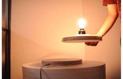
With independent implementation, there is a danger of fire. You need to turn the switch over, install an incandescent lamp next to the wireless power transmission device and enjoy the light show.
Wireless transmission through the solar energy system
Traditional wired configurations of energy sales typically require wires between distributed devices and consumer units. This creates many limitations as the cost of system cabling costs. Losses incurred in the transfer. As well as waste in distribution. Only the resistance of the transmission line leads to a loss of about 20-30% of the generated energy.
One of the most advanced wireless power transmission systems is based on the transmission of solar energy using a microwave or laser beam. The satellite is placed in a geostationary orbit and consists of photovoltaic cells. They convert sunlight to electrical current, which is used to power the microwave generator. And, accordingly, it implements the power of microwaves. This voltage is transmitted using radio communications and received at the base station. It is a combination of antenna and rectifier. And converted back to electricity. Requires AC or DC power. A satellite can transmit up to 10 MW of radio frequency power.
If we talk about the distribution system of direct current, then even this is impossible. Since this requires a connector between the power source and the device. There is such a picture: the system is completely devoid of wires, where you can get AC power in houses without any additional devices. Where it is possible to charge your mobile phone without having to physically connect to the jack. Of course, such a system is possible. And many modern researchers are trying to create something modernized, while exploring the role of developing new methods for wireless transmission of electricity from a distance. Although, from the point of view of the economic component, it will not be entirely beneficial for states if they introduce such devices everywhere and replace standard electricity with natural electricity.
The origins and examples of wireless systems
This concept, in fact, is not new. This whole idea was developed by Nicholas Tesla in 1893. When he developed the lighting vacuum lamp system using wireless transmission technology. It is impossible to imagine that the world existed without various sources of charging, which are expressed in a material form. To make possible mobile phones, home robots, MP3 players, a computer, laptops and other transportable gadgets that would charge on their own, without any additional connections, freeing users from permanent wires. Some of these devices may not even require a lot of elements. The history of wireless energy transmission is quite saturated, and, mainly, thanks to the development of Tesla, Volta, etc. But, today this remains only data in physical science.
The basic principle is to convert AC power to DC voltage using rectifiers and filters. And then - in return to the original value at high frequency using inverters. This low-voltage, with higher fluctuations, AC power then passes from the primary transformer to the secondary one. Converts to direct voltage using a rectifier, filter and regulator. The AC signal becomes direct due to the sound of current. As well as using the bridge rectifier section. The resulting DC signal passes through a feedback winding, which acts as a generator circuit. At the same time, it forces the transistor to conduct it into the primary converter in the direction from left to right. When the current passes through the feedback winding, the corresponding current flows to the primary part of the transformer from right to left.
Thus, the ultrasonic method of energy transfer works. The signal is generated through the primary converter for both half-periods of alternating current warning. Sound frequency depends on the quantitative indicators of oscillation of the generator circuits. This AC signal appears on the secondary side of the transformer. And when it is connected to the primary converter of another object, the AC voltage is 25 kHz. An indication appears through it in a step-down transformer.
This AC voltage is balanced using a bridge rectifier. And then it is filtered and adjusted to get a 5V output for controlling the LED. The output voltage of 12 V from the capacitor is used to power the DC fan motor for its operation. , , - . , , .