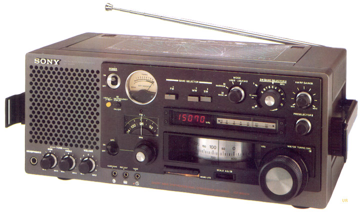
There are several schemes for constructing radio receivers. Moreover, it does not matter for what purpose they are used - as a receiver of broadcasting stations or as a signal in a control system kit. There are superheterodyne receivers and direct amplifiers. The direct gain receiver circuit uses only one type of vibration transducer — sometimes even the simplest detector. In fact, this is a detector receiver, only a little advanced. If you pay attention to the design of the radio, you can see that first the high-frequency signal is amplified, and then the low-frequency signal (for output to the speaker).
Features of superheterodynes
Due to the fact that spurious oscillations can occur, the possibility of amplification of high-frequency oscillations within small limits is limited. This is especially true when building short-wave receivers. Resonant structures are best used as a high-frequency amplifier. But in them it is necessary to make a complete reconfiguration of all the oscillatory circuits that are in the design, when the frequency changes.
As a result, the design of the radio receiver is significantly complicated, as well as its use. But these shortcomings can be eliminated using the method of converting received oscillations into one stable and fixed frequency. Moreover, the frequency is usually reduced, this allows to achieve a high gain level. It is at this frequency that the resonant amplifier is tuned. This technique is used in modern superheterodyne receivers. Only a fixed frequency is called intermediate.
Frequency Conversion Method
And now you need to consider the above-mentioned method of frequency conversion in radios. Suppose there are two types of oscillations, their frequencies are different. When these oscillations add up, a beating appears. The signal during addition then increases in amplitude, then decreases. If you pay attention to the graph that characterizes this phenomenon, you can see a completely different period. And this is the period of the beating. Moreover, this period is much longer than a similar characteristic of any of the fluctuations that developed. Accordingly, with frequencies, the opposite is true - for the sum of the oscillations it is less.
The beat frequency is easy to calculate. It is equal to the difference in the frequencies of oscillations that developed. Moreover, with an increase in the difference, the beat frequency increases. It follows that when choosing a relatively large difference in the components of the frequencies, high-frequency beats are obtained. For example, there are two oscillations - 300 meters (this is 1 MHz) and 205 meters (this is 1, 46 MHz). When combined, it turns out that the beat frequency will be 460 kHz or 652 meters.
Detection
But superheterodyne-type receivers always have a detector. The beats that result from the addition of two different vibrations have a period. And it is fully consistent with the intermediate frequency. But these are not harmonic oscillations of the intermediate frequency, in order to obtain them, it is necessary to carry out the detection procedure. Please note that from the modulated signal the detector only detects vibrations with a modulation frequency. But in the case of beats, everything is a little different - the so-called difference frequency oscillations are released. It is equal to the difference in frequencies that add up. This method of transformation is called the method of heterodyning or mixing.
Implementation of the method when operating the receiver
Let’s say, oscillations from a radio station come to the radio circuit. In order to carry out the transformations, it is necessary to create several auxiliary high-frequency oscillations. Next, the local oscillator frequency is selected. In this case, the difference of the summed frequencies should be, for example, 460 kHz. Next, you need to add the oscillations and apply them to the detector lamp (or semiconductor). In this case, the difference oscillation frequency (value 460 kHz) is obtained in the circuit connected to the anode circuit. It is necessary to pay attention to the fact that this circuit is tuned to operate at a difference frequency.
Using a high-frequency amplifier, you can convert the signal. Its amplitude increases significantly. The amplifier used for this is called the IF amplifier (intermediate frequency amplifier). It can be found in all receivers of the superheterodyne type.
Practical Triode Circuit
In order to perform frequency conversion, you can use the simplest circuit on a single lamp-triode. The oscillations that come from the antenna, through a coil, fall on the control grid of the lamp-detector. A separate signal comes from the local oscillator, it is superimposed on top of the main one. An oscillating circuit is installed in the anode circuit of the detector lamp - it is tuned to the difference frequency. When detecting, oscillations are obtained, which are further amplified in the IFA.
But designs on radio tubes are used very rarely today - these elements are outdated, it is problematic to get them. But it is convenient to consider all the physical processes that occur in the structure. heptodes, triode-heptodes, pentodes are often used as a detector. The semiconductor triode circuit is very similar to the one in which the lamp is used. The supply voltage is less and the winding data of the inductors.
Heptode inverter
A heptode is a lamp with several grids, cathodes and anodes. In fact, these are two radio tubes enclosed in one glass cylinder. The electronic flux of these lamps is also common. In the first lamp, oscillation is excited - this allows you to get rid of the use of a separate local oscillator. But in the second, the vibrations coming from the antenna and heterodyne are mixed. Beats are obtained, oscillations with a difference frequency are extracted from them.
Typically, the lamps in the diagrams are separated by a dashed line. The two lower grids are connected to the cathode by means of several elements - a classical feedback circuit is obtained. But the control grid directly of the local oscillator is connected to the oscillatory circuit. In the presence of feedback, current and oscillations occur.
The current penetrates through the second grid and the oscillation is transferred to the second lamp. All signals that come from the antenna arrive at the fourth grid. Grids No. 3 and No. 5 are interconnected inside the base and a constant voltage on them. This is a kind of screens located between two lamps. The result is that the second lamp is fully shielded. Tuning a superheterodyne receiver is generally not required. The main thing is to configure the bandpass filters.
Processes in the circuit
The current oscillates, they are created by the first lamp. In this case, there is a change in all parameters of the second radio tube. It is in it that all vibrations are mixed - from the antenna and the local oscillator. There is a generation of oscillations with a difference frequency. An oscillatory circuit is included in the anode circuit - it is tuned precisely to this frequency. Next, the oscillation is extracted from the current of the anode. And already after these processes, a signal is fed to the input of the amplifier.
Using special conversion lamps, a significant simplification of the design of the superheterodyne occurs. The number of lamps is reduced, several difficulties that may arise during the operation of the circuit using a separate local oscillator are eliminated. Everything discussed above relates to transformations of unmodulated oscillation (without speech and music). So much easier to consider the principle of operation of the device.
Modulated signals
In the case when the modulated oscillation is converted, everything is done a little differently. The oscillations of the local oscillator have a constant amplitude. Fluctuations in the IF and beats are modulated, as well as in the carrier. To convert the modulated signal into sound, another detection is necessary. For this reason, in superheterodyne HF receivers, after amplification is applied, a signal is supplied to the second detector. And only after it the modulation signal is fed to the headphone or input VLF (low-frequency amplifier).
One or two resonance-type cascades are present in the design of the amplifier. Typically, tuned transformers are used. Moreover, two windings are configured at once, and not one. Due to this, it is possible to achieve a more favorable shape of the resonance curve. Increases the sensitivity and selectivity of the receiving device. These transformers, whose windings are tuned, are called bandpass filters. They are tuned using an adjustable core or a tuning capacitor. They are set up once and do not need to be touched during operation of the receiver.
Local oscillator frequency
Now let's look at a simple superheterodyne receiver on a lamp or transistor. You can change the frequency of the local oscillator in the desired range. And it must be selected in such a way that with any frequency oscillations that come from the antenna, the same value of the intermediate frequency is obtained. When superheterodyne is tuned, the frequency of the amplified oscillation is adjusted to a specific resonant amplifier. It turns out a clear advantage - there is no need to configure a large number of interlamp oscillatory circuits. It is enough to configure the local oscillator circuit and the input circuit. There is a significant simplification of the setup.
Intermediate frequency
To obtain a fixed IF when working at any frequency that is in the operating range of the receiver, it is necessary to shift the oscillations of the local oscillator. As a rule, in superheterodyne radios, an IF of 460 kHz is used. 110 kHz is much less commonly used. This frequency shows the value by which the ranges of the local oscillator and the input circuit differ.
With the help of resonant amplification, an increase in the sensitivity and selectivity of the device occurs. And thanks to the use of the transformation of the incoming oscillations, it is possible to improve the selectivity indicator. Very often, two radio stations operating relatively close (in frequency) interfere with each other. Such properties need to be considered if you plan to assemble a homemade superheterodyne receiver.
How is the reception of stations
Now we can consider a specific example to understand the principle of operation of a superheterodyne receiver. Suppose an IF of 460 kHz is used. And the station operates at a frequency of 1 MHz (1000 kHz). And it is hindered by a weak station, which broadcasts at a frequency of 1010 kHz. The frequency difference is 1%. In order to achieve an IF equal to 460 kHz, it is necessary to tune the local oscillator to 1.46 MHz. In this case, the interfering radio station will give an IF equal to only 450 kHz.
And now you can see that the signals of the two stations differ by more than 2%. Two signals ran away, this happened using frequency converters. Reception of the main station was simplified, selectivity of the radio receiver improved.
Now you know all the principles of superheterodyne receivers. In modern radios, everything is much simpler - you need to use only one chip to build. And there are several devices assembled on it on a semiconductor crystal - detectors, local oscillators, amplifiers HF, LF, IF. It remains only to add an oscillatory circuit and several capacitors, resistors. And a complete receiver is assembled.