In this article, we will talk about how to make a tube headphone amplifier on your own. Many music lovers refuse modern amplifiers, since they do not consider the weight they produce as high-quality. It is much nicer to listen to the so-called “tube” sound - it is louder, richer, it even has some hidden warmth.
And the appearance of the tube amplifier is much more interesting than transistor or on microcircuits. It glows in the dark, sometimes emitting crackles when the lamps warm up. And the installation can be performed in any way - at least mounted, at least on a printed PCB. The article will discuss several methods of manufacturing an amplifier.
Case - which one to choose?
For tube technology, aluminum is the ideal material - it is outwardly attractive, and working with it is a pleasure. But you can use galvanized steel - only it is thinner, you have to make stiffeners. But it is allowed to use cheaper materials - plywood and plastic are suitable. You can use ready-made cases from old equipment and even plywood boxes. The main thing is that the dimensions are suitable - all the details should fit in the case.
Please note that when making a tube headphone amplifier for your own hands, you will need to use a high voltage power source. At least 120-150 V will have to be fed to the anodes of the lamps. And it is desirable for compactness to fit everything in one case. And in order to avoid any background noise in the headphones, it is necessary to shield the power supply from the main structural elements, especially from the output sound transformer (if any).
Production of aluminum housing
As you know, you can make a tube headphone amplifier with your own hands on any basis. But aluminum will look much more attractive. Therefore, you need to find a suitable material - it should not be thin so as not to bend under the weight of the installed parts. You will need to make a box of aluminum. It is better to make the joints with the help of welding - after it is necessary to carefully process the seams so that they do not stand out.
Then, after the formation of the box, you need to install a partition inside - it will serve as a screen between the power supply and the amplifier assembly. In this screen, make a hole in which you subsequently lay the power wires. Schedule the position of all elements - lamps, transformers, regulators, switches and sockets. In the case of surface mounting, passive components — resistors, capacitors, etc. — will be installed on all of these elements. But you can also use mounting on a printed circuit board - however, difficulties may arise. All the moments now and consider.
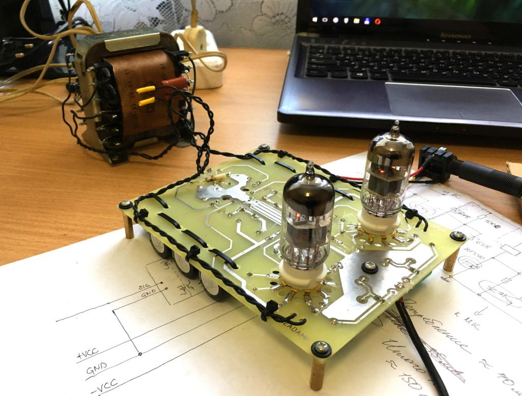
Printed circuit
This installation method is quite attractive, but you will have to clearly mark the position of the socket for the lamp and the holes in the housing. If they do not match, then installing the lamps and replacing them will be a problem. When using this mounting method, all resistors, capacitors and diodes, as well as lamp slots, are installed on the printed circuit board. All other components - jack type jacks, tone and volume controls, tulips, are mounted on the side walls and connected to the board using shielded wires.
In the manufacture of the printed circuit board, a solution of ferric chloride, a permanent marker, and also foil textolite will be required. The main thing is to correctly mark the tracks. They should not be too long - this can cause the appearance of an extraneous background. In order to completely get rid of the background, you can put a screen of thin metal on top of the tracks at a distance of 0.5 cm (just not to touch). It must be connected to a common wire (minus power).
Mounted Mounting
This type of installation, although it does not differ in beauty, is reliable and allows you to reduce the length of the conclusions of the elements. This favorably affects the operation of the device. In the manufacture of a 6H6P headphone tube amplifier (this is a double triode), a circuit can be implemented in which there will be only two lamps. Moreover, two halves will be involved - one as a pre-amplifier with a tone control, the second will be a terminal cascade. It is recommended to use transformers - they can reduce the resistance of the cascade.
In order to put into practice the hinged installation, you just need to make holes for the lamp sockets. But you need to make holes as close to each other as possible - this will get rid of the possible appearance of the background during operation. Then you outline the holes for installing variable resistors and jacks for connecting headphones and signal sources. Be sure to make holes for the power transformer and sound output mounts. And don't forget about electrolytic capacitors. In the part of the housing where you plan to install the power supply, you need to make holes for the wire and switch. It is advisable to install a fuse. You can use self-healing, since it has a low cost.
Choosing a circuit for an amplifier
If you pay attention to what kind of amateur radio circuits are used in their designs, you can see that the choice is not very large. Differences can be in the lamps that are used in the design. if you make a 6N6P headphone tube amplifier, you will get a relatively small-sized device. But in the case of using a lamp of type 6H6C, the dimensions of the structure increase - their sockets differ, and significantly.
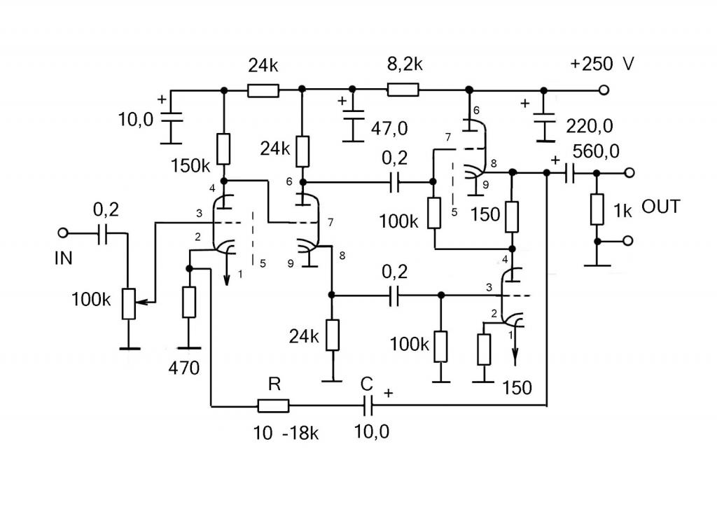
The classic circuit is a preamplifier on 6N6P or 6N2P lamps. Some music lovers use 6N23P - they justify their choice by the fact that her sound is much more pleasant. The output stage can be built on a similar triode or pentode type 6P14P. In this case, you can achieve greater gain, but when using headphones as a load, this is not very necessary.
By the way, there are finger lamps - their sizes are much smaller than those that were given in the article. For them, you do not need to install sockets, they just solder into the board. Such lamps are convenient to use in cases where the space for installation is limited. But these lamps will not be visible - they should be hidden inside a well-ventilated case.
Power Supply Fabrication
Please note that any, even home-made tube headphone amplifier needs power. There must be three windings in the transformer:
- Glow - alternating voltage 6.3 V.
- Anode - voltage from 150 to 300 V.
- Network - to connect to an outlet.
Be sure to install a fuse and a switch in the circuit - this will make using the amplifier as safe as possible. Please note that all windings must be laid tightly. Also, the presence of gaps in the core is not allowed. This may cause abnormal noise. The transformer should work silently - this is the main condition.
Rectifier and filters
Then you need to make holes for the installation of electrolytic capacitors - they are used in power supplies to get rid of the alternating current component. As a rectifier, you can use an assembly consisting of four semiconductor diodes. It is called a "selenium rectifier." The case is made of thin aluminum, four terminals to which an AC source and load are connected. The design is not very complicated, but getting such a device is becoming increasingly difficult.
Therefore, it is best to use conventional semiconductor diodes as the rectifier of a portable tube headphone amplifier. The only condition is that the reverse voltage should be 300 V and higher. For lamp technology, high voltages are normal. It is recommended to install additional chokes - they will get rid of high-frequency interference that can penetrate from the network. This is true for cases when the amplifier is planned to be used in conjunction with a laptop, personal computer, and any other equipment that uses switching power supplies.
Filament windings
The filament voltage for most of the radios is 6.3 V. The maximum allowable value is 7 V. But there are also lamps that need 12.6 V for filament windings (for example, GU-50). But these are lamps that are used exclusively in powerful equipment and for our design they are not applicable. The filament winding must be wound with a thick wire - to provide all circuits with power. In addition, a lamp (or LED) can also be powered from it, which will signal that the amplifier is turned on / off.
Sometimes in the literature you can find the recommendations of experts - to rectify the current before applying the lamp to the glows. This is a good solution to get rid of extraneous noise arising during operation. The fact is that the filament, like a speaker, “buzzes” a little when powered by an AC source. It oscillates with a frequency of about 50 Hz. These fluctuations can affect the performance of the ULF. To get rid of them, it is enough to install a bridge rectifier and several electrolytic capacitors. Then just the filament will not vibrate.
Amplifier assembly
And now let's start the assembly of the amplifier - this is a painstaking task, but it is very simple. Even the best tube headphone amplifiers are assembled according to the classical schemes that we talked about above. Choosing a specific scheme, you can begin to implement it. Collect all the items you need. Install variable resistors and you can start assembling.
The first step is to lay the power supply busbars. To save money, sometimes one of the wires is connected to the housing. In our case, the power is supplied by direct current, so the minus must be connected to the case. Therefore, on each lamp socket, one of the terminals of the filament must be connected to the housing. The second output is plus from the power source. Then, when all the tires are in place, you can proceed with the installation of passive components.
Mounting elements
The first step is to make the connections of the circuits, which can be the cause of the appearance of an extraneous background. When you connect the headphones to the tube amplifier, a characteristic sound may be heard, which indicates that there is a poor connection in the circuits. Connect variable resistors to the circuit elements using shielded wires - make sure that the wire without braid is as short as possible. Lay the wires neatly, you can use the clips for fastening.
Then install resistors and capacitors - the high-voltage (anode) part must be made the very last. To facilitate installation, you can use cylindrical electrolytic capacitors type VZR KE-2M. They are secured to the housing with a nut. The minus is the capacitor housing, plus the central core. It is with its help that the installation can be facilitated - it connects to the “+ 300V” from the power source. And then resistors are soldered to this core, the second output of which is connected to the anodes of the lamps.
Installation completion
Now you need to implement the connection of headphones to the tube amplifier - this is done using jack-type plugs. Immediately you need to make a reservation that using a 3.5 mm connector is inconvenient - it is difficult to put it on, and soldering is also problematic. Therefore, it is better to use 6.5 mm connectors - they look beautiful on an aluminum case. If you are making a transformerless tube headphone amplifier, you need to connect the load to the anode circuit.
It is recommended before starting work to determine whether a mixer is needed. This device, with the help of which merges several signals into a single whole. In other words, you can take the signal from the microphone, computer and guitar, adjust the gain and apply to the input of the ultrasonic scanner. Therefore, if you need to make several inputs, you will need to install additional connectors such as "tulip" or "jack". And for each input volume control is done - for this purpose, separate variable resistors are installed.
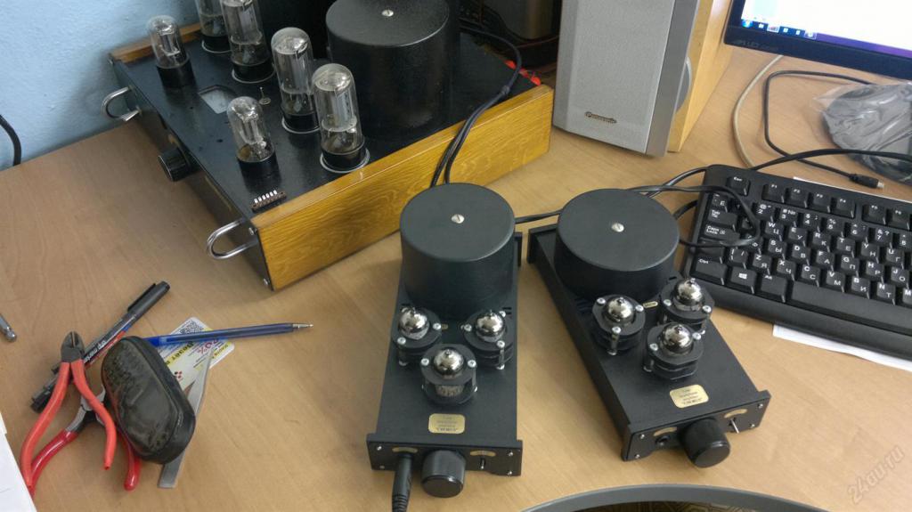
Stereo ULF
And one moment. In the manufacture of a stereo tube headphone amplifier on 6Zh1P or a similar lamp, it is necessary to use variable paired resistors - two in one. In other words, there should be two sliders on one lever. With the help of such a device, it is possible to simultaneously adjust the gain along two channels at once.
If the amplifier is stereo, then a separate preamplifier is used for each signal source. The end cascade may be common. But the easiest way to implement a stereo amplifier is to make two monophonic devices. One signal from the left channel, the second - from the right. By a similar scheme, you can make an amplifier for the subwoofer. You just need to add a low-pass filter to the design. But in the manufacture of a simple tube amplifier for headphones with your own hands, this is not required.
Sound transformer
In the manufacture of a lamp ULF according to the classical scheme, it is necessary to use transformers of the TVZ type. Such were installed earlier on amplifiers in radios and radios. If you look closely, you can see that there are practically no differences from mains transformers. And now in more detail:
- The primary voltage of the mains and sound transformers is about 250 V.
- The secondary winding voltage is about 9-10 V.
In other words, even the Chinese network can be used as an audio transformer. They can be found both in cheap speakers and in various devices. You just need to pay attention to the quality of the steel from which the core is made. For transformers such as TVZ or TVK (used for personnel scanning of tube TVs), steel is much better than that of Chinese counterparts.
In that case, if a stereo amplifier circuit is used, one feature must be taken into account. Connect the secondary windings of the transformers for the tube headphone amplifier must be in series. The midpoint connects to the device case. The second conclusion is the left channel, and the third is the right channel. Such an amplifier can also be used as a preliminary stage for a home speaker system. Several signals from various sources can be connected to it at once.
Finally
But you can independently make not only from improvised materials a tube headphone amplifier. A kit for the manufacture of such devices can be purchased for a relatively small price. Of course, giving money for what can be found at any landfill is stupid. The most difficult thing at work is the manufacture of the case. It’s easy to work with aluminum, but welding is problematic - it’s easier to find a person who is involved in this business. You can, of course, use a bolted connection. But it turns out to be much weaker.
The device does not require settings, it’s quite simple to connect the headphones to the tube amplifier - everything starts working literally right away. If you doubt your abilities, then first try to make a "draft" version - so to speak, on the knee. After manufacturing such a device, several experiments can be done to help determine the necessary parameters of the elements. The fact is that by selecting capacitors, you can change the tone - increase or decrease the frequency of the reproduced sound.
The amplifier, made according to the classical scheme, will work for a long time, because the life of a radio tube is about 1000 hours. And you can replace it in just a couple of seconds. You can even connect a vinyl player to such a device - this will be relevant for lovers of "antiquity." But the output that connects to the headphones can be connected to the input of the sound card - this will allow you to digitize any vinyl record.