Magnetic starters and contactors are devices designed for switching power circuits. By the way, about the name and characteristics of starters and contactors: you will not find such significant differences between the magnetic starter device and the contactor. It was just that in the Soviet Union there were starters that held currents from 10 A to 400 A, and contactors that held currents from 100 A to 4,800 A. After that, magnetic starters began to be classified as low-power and small-sized contactors. Next, we will tell more about the device and the principle of operation of the magnetic starter.
What are magnetic starters used for?
The meaning of their application is different. For example, it is not recommended to install switching equipment in machine tools in paint shops, pumping units that transfer fuel, and similar premises. The danger lies in the fact that whatever the device and principle of operation of the magnetic starter, breaking the load, it creates a spark and arc discharges that can ignite, like a spark in a lighter, flammable vapors. To do this, all starters are placed in a separate, almost hermetically sealed room. The operating voltage of the starters is usually limited to 12 volts, so that the buttons that are located in the danger zone do not cause sparks. Also, starters are used in various schemes of protection, deadlock, reverse and the like. Below we give examples of some of these schemes.
Device
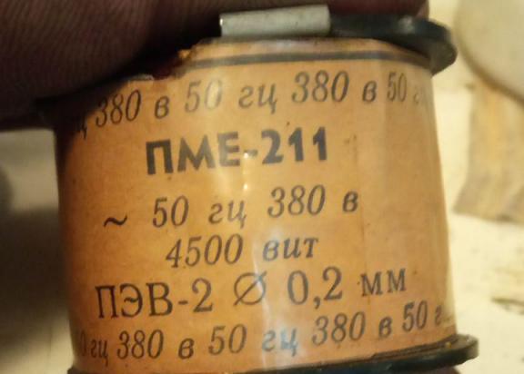
We will disassemble the magnetic starter device using the PME-211 model as an example. This type, although morally obsolete, is often found in equipment and machines from the Soviet era. The PME magnetic starter device is quite simple and just right for mastering. Removing the protective cover, we see contact groups.
They consist of contacts, which, in turn, are divided into movable (mounted in a movable frame with an anchor) and fixed (mounted on the contactor head). Note that all contacts on the moving part are spring-loaded. This is done for the best contact between the pads, that is, heat-resistant deposition on the contact. Having removed the contactor head, we see that below it is an anchor directly opposite the magnetic circuit with the coil. A drop spring is installed between them, which is necessary in the device of the magnetic starter in order to bring it to a normal state. This spring is strong enough to sharply bring the starter into such a state and break the load to reduce the exposure time of the arcing. It is weak enough to overload the coil, and also prevent the magnetic circuit from closing and snug against each other. Due to improperly selected springs, the starter is quite noisy. When repairing and servicing this feature is worth considering. The coil is usually marked with information about it, operating voltage, type of current, number of turns, frequency.
Operating principle
The device of a magnetic starter implies working according to this principle: a supply voltage is supplied to the coil, which is installed on the magnetic circuit. The magnetic core is magnetized, attracting the anchor, and that, in turn, pulls a frame on which the contact groups are fixed. The device and operation of the magnetic starter are based on the action of an electromagnet. When retracting the armature, contact groups of power contacts are closed.
Auxiliary contacts are divided into 2 types:
- normally closed, that is, those that, in the absence of voltage on the coil, open, turning off the power or forming a negative signal, depending on how and what it is connected to;
- normally open, which, on the contrary, close, thereby affecting the control circuit or giving a positive signal.
When the voltage is removed, the starter comes to normal, and the contacts are discarded under the action of a return spring. All contacts of the magnetic starter installed in the dielectric frame, as a rule, made of heat-resistant plastic, are spring-loaded to ensure the best fit between movable and fixed contacts. A magnetic starter is simply arranged, and the principle of its operation is based on an electromagnet.
How to distinguish normally closed from normally open contacts?
On PME starters, they are open and visible. But we will show by the example of the PML starter how to do this in the case when the contacts are closed.
The multimeter is set to dialing mode, and voltage is not applied to the starter. This is his normal condition. Then contact groups alternately ring. Those that do not ring are normally open, and which, conversely, ring are normally closed.
Service and Repair
The design and principle of the magnetic starter means regular maintenance and repair. It is worth doing it as planned, as over time deposits appear on the pads. In this regard, the magnetic circuit can be oxidized under the influence of a damp environment, and exfoliated rust forms abrasive dust, which, falling into the moving parts, leads to excessive wear.
Visual inspection
It is done in order to detect cracks, chips, melted places. Also, over time, the integrity of the shell into which the starter was installed may be violated, and the presence of excessive dust or crystalline salt growths will indicate this. It is worthwhile to understand that the starter bounces a little when it is turned on and off, which means that the fastener elements should not be cracked. Otherwise, the starter can simply fall off and turn on the load. Or include, for example, two of the three phases, which will certainly burn the engine.
Contact groups
Opening the protective cover, we can see the contact groups. Depending on the purpose and device of the magnetic starter, they can be of different sizes and with solders made of different metal. Slight soot is removed with a rag or file. It is impossible to use the skin here, since it is difficult to keep track of the angle of inclination, the plane will not be sustained. Because of this, the contact will be loose, which means that the contact pads will heat up. Deposits and shells are cleaned with a file, and then with a small file.
Anchor, magnetic circuit and coil
The anchor and the magnetic circuit should not have traces of rust, and the plates from which they are assembled must be securely riveted. The coil, in turn, must be dry and free from traces of carbon (in the case of paper used as external insulation) or reflow if it is filled with plastic. If such signs are found, it is better to replace it.
Mounting of moving parts, grooves
Grooves should not have cracks, chips or dust. Otherwise, this can cause biting and slow rejection of the moving contacts from the stationary ones. Elements installed in the grooves should slightly play and move freely along the groove. It is also worth noting that the anchor, like the magnetic circuit, is not installed rigidly. This is done with the aim that the magnetic circuit can easily magnetize the anchor tightly and reliably. Slight swaying of the anchor in its groove is normal. If there is no wiggle, it means that a lot of dust has accumulated there or the mount is deformed. This must certainly be eliminated in order to ensure uninterrupted performance of the device by its functional purpose.
Magnetic starter devices according to the principle of the circuit
Typically, such a scheme is used when the voltage loss in a particular equipment is critical. For example, a household single-phase pump with a starting winding. If the power suddenly disappears and after a few seconds appears again, the engine will simply burn out. For such defenses, the following scheme exists.
The protection circuit from self-switching works as follows: the voltage to the starter coil passes through the normally closed contact of the “stop” button, which is designated as KNS in the diagram, to the normally open contact of the “start” button. Between the “stop” and “start” buttons, a wire is output that goes to the normally open auxiliary contact on the starter. On the other side of the contact, 2 wires are connected: an output after the “start” button and a power wire to the coil. When the “start” button is pressed, power is supplied to bypass the normally open contact to the coil, as a result of which the contact closes. When we release the “start” button, the starter powers itself through an auxiliary contact. When the “stop” button is pressed, the coil loses power, due to which the contact opens.
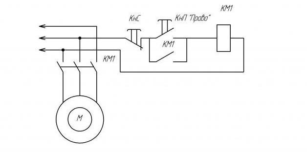
Deadlock scheme
Typically, this circuit is used with two starters in pairs to enable reverse of the motor or, for example, to limit the operation of one function while the other is on.
The power to the control circuit is supplied to the normally closed contact of the “stop” button (KNS). Then there is a branching into normally open contacts of the KnP “right” and Knp “left”. And the power comes to the normally open contact of the KnP “right” through the normally closed contact of the KnP “left”. And vice versa. This is done to avoid the simultaneous inclusion of both starters, as protection against accidental clicks. If the starters turn on at the same time, since the reverse works due to a change of two wires, a short circuit will occur in some places, which will cause significant harm to contact groups.
Then the wire that goes to the normally open contact of the KnP “right” goes to the auxiliary normally open contact of the starter. Then, on the other side of this starter, the output from the “right” circuit breaker is brought in and a jumper is installed leading to the coil contact. The second contact of the coil is passed through the normally closed auxiliary contact of the second starter. This is done for reinsurance, to exclude the possibility of simultaneous inclusion of starters. The power supply of the second starter is arranged in a similar way. Before coming to the normally open contact of the KnP “left”, it is passed through the normally closed contact of the KnP “right”. Then, in a similar way, it connects to the second starter. On the one hand, a normally open contact group leads the wire going to the left “KNP”, and on the opposite side - which goes after the left KNP. A jumper is installed leading to the coil contact. The second contact of the coil is passed through the normally closed contact of the first starter.
In conclusion, we can say that there are a great many methods of using starters. We have cited the most widespread ones that are used in industries, and can also be useful in everyday life. In any case, no matter how you use the device of the contactor, the magnetic starter, before buying, you should calculate the current that will pass through its power contacts, set the operating voltage of the coil, the type of current. It is also worth considering dust and moisture protection of the starter from harmful environmental factors. It is imperative to inspect the starters on a planned and unscheduled basis, when the equipment that he supplies is worn out. Sometimes it is the starter that causes the breakdown of equipment.