A thyristor is a semiconductor element made on the basis of a semiconductor single crystal, having three or more pn junctions and two stable states: a state of low conductivity, which is called closed; and the state of high conductivity is open.
An amateur radio amateur may ask a question: “How is the thyristor checked?” In this article, we will examine the methodology for testing this semiconductor element. We will also analyze what kind of device is needed to check thyristors.
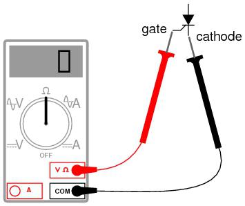
There are several methods for testing semiconductor devices. A preliminary check of the thyristor can be carried out using the following instruments: a digital multimeter, tester or ohmmeter. The multimeter must be turned on in the “ringing” mode of the diodes, and the tester in the resistance measurement mode. Using these devices, it is possible to check the thyristor transitions between the control electrode and the cathode, as well as between the anode and cathode. The value of the transition resistance of the semiconductor element between the control electrode and the cathode should be 50-500 Ohms. The value of this resistance is approximately the same for both direct and reverse measurements. The higher the resistance value, the more sensitive the semiconductor thyristor. In other words, the device needs a small current value on the control electrode in order to switch from a closed to an open state. A serviceable thyristor has a resistance value between the anode-cathode electrodes in both direct and reverse metering, which tends to infinity.
A preliminary check of the thyristor gives the likelihood that a used semiconductor element may contain a burnt cathode – anode junction. Measuring instruments cannot determine such a malfunction.
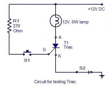
The main check of the thyristor is carried out using additional power sources. With this operation, the malfunction of the semiconductor device is completely eliminated. The thyristor goes into an open state if a short pulse necessary to open an element is passed through a cathode — a control electrode. For this, a circuit is going to check the thyristors. There are many such schemes, let's consider the most elementary. To do this, we use a power source, indicator light, two switches and a resistor. The circuit can be assembled on a test board, or by mounted mounting. We assemble the circuit: minus the power source (5-25 V), we feed it to the cathode of the thyristor. Plus the source through the normally closed button K1 and through the indicator lamp to the anode of the device.
We connect a resistor to the output of the control electrode, the second contact of which is connected through the normally open button K2 between the lamp and button K1. The resistance value is selected so that the flowing current is sufficient to turn on the device. Everything, the circuit is ready, we begin the verification. To do this, close the K2 button, the control current will go along the circuit: from the plus, through the buttons K1 and K2, through the resistor, through the control electrode, to the cathode and to the minus of the source. Thyristor opens. Release the K2 button. The indicator lamp lights up. We press the normally closed button K1, the load current circuit through the thyristor breaks, and it closes. The lamp goes out, the circuit returns to its original state.