Interference patterns are light or dark bands that are caused by beams in phase or out of phase with each other. Light and similar waves, when superimposed, add up if their phases coincide (both upward and downward), or they cancel each other out if they are in antiphase. These phenomena are called constructive and destructive interference, respectively. If a beam of monochromatic radiation, all waves of which have the same length, passes through two narrow slits (the experiment was first conducted in 1801 by Thomas Young, an English scientist who, thanks to him, came to the conclusion about the wave nature of light), the two resulting rays can be directed on a flat screen, on which instead of two overlapping spots interference fringes are formed - a pattern of evenly alternating light and dark areas. This phenomenon is used, for example, in all optical interferometers.
Superposition
The defining characteristic of all waves is the superposition, which describes the behavior of superimposed waves. Its principle is that when more than two waves are superimposed in space, the resulting perturbation is equal to the algebraic sum of the individual perturbations. Sometimes, with large disturbances, this rule is violated. This simple behavior leads to a series of effects called interference phenomena.
The phenomenon of interference is characterized by two extreme cases. In the constructive maxima of the two waves coincide, and they are in phase with each other. The result of their superposition is an increase in perturbation. The amplitude of the resulting mixed wave is equal to the sum of the individual amplitudes. And, on the contrary, in destructive interference the maximum of one wave coincides with the minimum of the second - they are in antiphase. The amplitude of the combined wave is equal to the difference between the amplitudes of its components. In the case when they are equal, the destructive interference is complete, and the total perturbation of the medium is zero.
Jung's experiment
The interference pattern from two sources unambiguously indicates the presence of overlapping waves. Thomas Jung suggested that light is a wave that obeys the principle of superposition. His famous experimental achievement was the demonstration of constructive and destructive interference of light in 1801. The modern version of Jung’s experiment in essence differs only in that it uses coherent light sources. The laser evenly illuminates two parallel slits in an opaque surface. Light passing through them is observed on a remote screen. When the width between the slots significantly exceeds the wavelength, the rules of geometric optics are observed - two illuminated areas are visible on the screen. However, when the slots approach each other, the light diffracts, and the waves on the screen overlap each other. Diffraction itself is a consequence of the wave nature of light and another example of this effect.
Interference pattern
The principle of superposition determines the resulting intensity distribution on the illuminated screen. The interference pattern occurs when the path difference from the slit to the screen is equal to an integer number of wavelengths (0, λ, 2λ, ...). This difference ensures that the highs arrive simultaneously. Destructive interference occurs when the path difference equals an integer number of wavelengths shifted by half (λ / 2, 3λ / 2, ...). Jung used geometric arguments to show that superposition results in a series of equally spaced bands or areas of high intensity corresponding to areas of constructive interference separated by dark areas of complete destructive.
Hole spacing
An important geometry parameter with two slits is the ratio of the light wavelength λ to the distance d between the holes. If λ / d is much less than 1, then the distance between the bands will be small, and the effects of superposition will not be observed. Using closely spaced slots, Jung was able to separate the dark and light areas. Thus, he determined the wavelengths of the colors of visible light. Their extremely small value explains why these effects are observed only under certain conditions. To separate the sections of constructive and destructive interference, the distances between the sources of light waves must be very small.
Wavelength
Observing interference effects is challenging for two other reasons. Most light sources emit a continuous spectrum of wavelengths, resulting in the formation of multiple interference patterns superimposed on each other, each with its own interval between the bands. This eliminates the most pronounced effects, such as areas of complete darkness.
Coherence
In order for interference to be observed over an extended period of time, coherent light sources must be used. This means that radiation sources must maintain a constant phase ratio. For example, two harmonic waves of the same frequency always have a fixed phase relationship at each point in space - either in phase or in antiphase, or in some intermediate state. However, most light sources do not emit true harmonic waves. Instead, they emit light in which random phase changes occur millions of times per second. Such radiation is called incoherent.
The perfect source is a laser
Nevertheless, interference is observed when waves of two incoherent sources overlap in space, but interference patterns change randomly, together with a random phase shift. Light sensors, including eyes, cannot register a fast-changing image, but only a time-averaged intensity. The laser beam is almost monochromatic (i.e., consists of one wavelength) and highly coherent. It is an ideal light source for observing interference effects.
Frequency determination
After 1802, the wavelengths of visible light measured by Jung could be correlated with the insufficiently accurate speed of light available at that time to approximately calculate its frequency. For example, in green light it is about 6 × 10 14 Hz. This is many orders of magnitude higher than the frequency of mechanical vibrations. For comparison, a person can hear sound with frequencies up to 2 × 10 4 Hz. What exactly fluctuates at such a speed remained a mystery for the next 60 years.
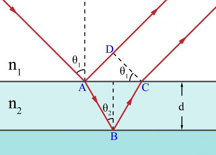
Thin Film Interference
The observed effects are not limited to the double slit geometry used by Thomas Young. When reflection and refraction of rays from two surfaces occurs, separated by a distance comparable to the wavelength, interference occurs in thin films. The role of the film between the surfaces can play a vacuum, air, any transparent liquids or solids. In visible light, interference effects are limited to sizes of the order of several micrometers. A well-known example of a film is a soap bubble. The light reflected from it is a superposition of two waves - one is reflected from the front surface, and the second from the back. They are superimposed in space and stacked with each other. Depending on the thickness of the soap film, two waves can interact constructively or destructively. A complete calculation of the interference pattern shows that for light with the same wavelength λ, constructive interference is observed for a film of thickness λ / 4, 3λ / 4, 5λ / 4, etc., and destructive interference is observed for λ / 2, λ, 3λ / 2, ...
Formulas for calculating
The phenomenon of interference has found many applications, so it is important to understand the basic equations related to it. The following formulas allow you to calculate various values associated with interference for the two most common cases.
The arrangement of light bands in Jung's experiment, i.e., areas with constructive interference, can be calculated using the expression: y light. = (λL / d) m, where λ is the wavelength; m = 1, 2, 3, ...; d is the distance between the cracks; L is the distance to the target.
The location of dark bands, i.e., areas of destructive interaction, is determined by the formula: y dark. = (λL / d) (m + 1/2).
For another type of interference — in thin films — the presence of constructive or destructive overlap determines the phase shift of the reflected waves, which depends on the thickness of the film and its refractive index. The first equation describes the absence of such a shift, and the second describes a half wavelength shift:
2nt = mλ;
2nt = (m + 1/2) λ.
Here λ is the wavelength; m = 1, 2, 3, ...; t is the path traveled in the film; n is the refractive index.
Observation in nature
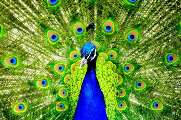
When the sun illuminates the soap bubble, you can see bright colored stripes, as different wavelengths undergo destructive interference and are removed from reflection. The remaining reflected light appears to complement the distant colors. For example, if as a result of destructive interference there is no red component, then the reflection will be blue. Thin films of oil on water produce a similar effect. In nature, the feathers of some birds, including peacocks and hummingbirds, and the shells of some beetles look rainbow, while changing color when changing the viewing angle. The physics of optics here consists in the interference of reflected light waves from thin layered structures or arrays of reflecting rods. Similarly, pearls and shells have an iris, thanks to the superposition of reflections from several layers of nacre. Gemstones, such as opal, exhibit beautiful interference patterns due to light scattering from regular structures formed by microscopic spherical particles.
Application
There are many technological applications of light interference phenomena in everyday life. The physics of camera optics is based on them. A conventional lens coating is a thin film. Its thickness and refraction of the rays are selected so as to produce destructive interference of the reflected visible light. More specialized coatings, consisting of several layers of thin films, are designed to transmit radiation only in a narrow wavelength range and, therefore, are used as light filters. Multilayer coatings are also used to increase the reflectivity of mirrors of astronomical telescopes, as well as laser optical resonators. Interferometry — the accurate measurement methods used to record small changes in relative distances — is based on observing the shifts of the dark and light bands created by reflected light. For example, measuring how the interference pattern changes, allows you to set the curvature of the surfaces of the optical components in fractions of the optical wavelength.