In the modern world of digital technology, programming is the basis for the operation of various computers, gadgets and other electronic equipment. And the ability to quickly and correctly draw up a block diagram of an algorithm acts as the foundation, the foundation of this science. Such a scheme is a graphical model of the processes that equipment needs to perform. It consists of separate function blocks that perform various purposes (start / end, input / output, function call, etc.).
Algorithm and Algorithmization
In fact, the algorithm is a simple instruction about in what sequence it is necessary to perform certain actions when processing the source data into the desired result. Along with this term, the concept of algorithms is often used . Under it is understood a set of methods and techniques for compiling a sequence for solving specific problems.
Often the algorithm is used not as an instruction for a computer, but as a scheme for performing any actions. This allows us to note the effectiveness and efficiency of this method of solution, correct possible errors, and also compare it with other similar solutions even before entering the computer. In addition, the algorithm provides a basis for compiling a program that must be written in a programming language in order to further implement the process of processing information on a PC. To date, two practical ways of constructing such sequences have gained fame. The first is a step-by-step verbal description, and the second is a block diagram of the problem algorithm. The first of them has received much less distribution. This is due to lack of clarity and verbosity. The second method, on the contrary, is a very convenient means of image sequence. It is widely distributed both in educational and in scientific literature.
Flowchart elements
The block diagram of the program algorithm is a sequence of graphic symbols that prescribe the performance of specific operations, as well as the relationships between them. Inside each such image, information about the task to be performed is indicated. The sizes and configuration of graphic symbols, as well as the sequence design sequence are regulated by GOST 19003-80 and GOST 19002-80.
Consider the main elements of the flowchart of the algorithm (the photo provides examples of their outline).
1. A process is a computational action or a sequence of such actions.
2. Solution - verification of a given condition.
3. Modification - the title of the cycle.
4. A predefined process is an appeal to a procedure.
5. Document - printing and data output.
6. Punch card - enter information.
7. Input / Output - Input / Output of data.
8. Connector - a break in the flow lines.
9. Start / End - start, end, stop, start, entry and exit are used in auxiliary algorithms.
10. Commentary - used to place explanatory inscriptions.
11. Vertical and horizontal flows - the direction of the sequence, the communication line between the blocks.
12. Merging - connecting threads.
13. Interstitial connector - a label symbolizing the transition to another sheet.
Drawing Rules
The construction of the flowchart of the algorithm is carried out according to the specific requirements prescribed by GOST. For example, when connecting graphic characters, only horizontal or vertical lines are used. Streams directed from right to left and from bottom to top are always marked with arrows. Other lines may not be marked. The distance between parallel flows should not be less than three millimeters, and between the other elements - not less than five millimeters. Block sizes must be a multiple of five. The horizontal to vertical ratio of the graphic symbol is 1.5. Sometimes equal to two is allowed. For convenience of description, graphic symbols should be numbered. By the nature of the connections, types of flowcharts of the linear, cyclic and branching structure algorithm are distinguished.
Variables, constants and memory cells
For a better understanding of the principle of the algorithm, you can consider the simplest machine. It consists of a memory consisting of cells; recording / reading head; CPU. What is the principle of operation of such a device? The head, having received an order from the processor, writes data to the cell or reads a constant. In the simplest case, it will be an arithmetic number. In addition, data structures, character strings, etc. can be constants. By a variable is meant a memory cell in which information is stored. During the execution of the algorithm, various data can be written in such a cell. Personal computers and other electronics are built on this principle. An algorithm for performing a task is a set of instructions for reading or writing information to these memory cells.
Arrays
Arrays are another kind of indexed variable. In fact, this is a collection of cells, which is united by a common designation. Arrays distinguish between two-dimensional, three-dimensional, etc. The simplest of them is a series of consecutive cells. Such an array has its own name. Each element has its own number - index. A constant written to a cell is called an array element.
The two-dimensional type in its arrangement of elements resembles a matrix. Cells in such an array are characterized by two indices (this resembles a chessboard with cell numbering). Three-dimensional and more structures are implemented according to the same principle.
Linear Algorithms
This type of sequence of the flowchart of algorithms (examples are given in this article) is characterized by execution from top to bottom. In this case, the machine performs the operations prescribed to it step by step. Each action is processed by the processor. In addition to calculations, if necessary, he orders the recording / reading head where and what to write and where to read from. The final result is recorded in memory cells, each of which has its own index and stores its own constant.
Branching algorithms
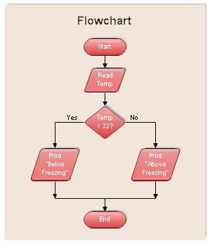
In practice, the linear type is extremely rare. Often it is necessary to organize a sequence that, depending on the given conditions, flows along one or another branch. The flowchart of the branched type algorithm contains a “Solution” element, due to which a certain condition is checked, and the more there are, the more branches the sequence has.
Algorithm Flowcharts: Examples
Let's consider how the branched algorithm functions. As an example, take the function: z = y / x. It can be seen from the condition that this equation has one limitation - it is impossible to divide by zero. So it is necessary to exclude this decision and warn the user about the error that has occurred. First, a block diagram of the algorithm is compiled. It will consist of seven blocks. The first graphic symbol is “Start”, the second is “Input”, here you should set the values of X and Y. Then the “Solution” block follows, it checks the condition: X = 0. In this case, the machine reconciles with the cell constant, if the input value matches it, then the algorithm will go along the "Yes" branch. In this case, control is transferred to the fourth block, and the machine gives an “error”, the work ends in the seventh “End” symbol. If the test result is negative, then the division process is carried out in the fifth graphic symbol and the value Z is determined. In the sixth block, the result is displayed on the screen.
Loop Algorithms
Often, when solving problems, it is necessary to repeat the execution of an operation according to the same dependence for various values of the variables and to make multiple passes through the same section of the circuit. Such sections are usually called cycles, and the algorithm is called cyclic. Using this method significantly reduces the sequence itself. Cyclic algorithms are usually divided into two types: with a previously unknown and a known number of such passes.
Branching Algorithm Solution Example
Consider an example in which a block diagram of an algorithm with an unknown number of passes is given in advance. To do this, the problem should be solved - indicate the smallest number of members of a series of natural numbers whose sum exceeds the number K. Such a block diagram of the algorithm consists of eight characters. First, enter the value of the number K (No. 2). Then, in block 3, the variable P receives the value "one", which means that it will begin the counting of natural numbers. And the cumulative amount C at the beginning gets the value "zero". Next, control is transferred to the fifth block, where the command is executed: C = C + P. That is, the values of cells C and P are summed up, and the result is overwritten in C. After adding the first member of this sequence in block No. 6, the condition is checked - does the sum exceed the given number K? If the condition is not met, then control is transferred to the fourth block, where one is added to the variable P and the transition is carried out again to block No. 5. This procedure will occur until the condition: C> K, that is, the accumulated amount will exceed the specified value. Variable P is a loop counter. Next, the transition to block No. 7, where the results of the work are printed.
Algorithms containing nested loop structures
Often with an algorithmic solution to the problem, there is a need to create a cycle that contains another cycle in its body. This is considered the norm. Such elements are called nested loop structures. Their order can be quite large. It is determined by the method, due to which the solution of the necessary problem is achieved. For example, when processing a one-dimensional array, as a rule, a block diagram of the algorithm is constructed without nesting loops. Nevertheless, in some cases, when solving such problems, it becomes necessary to choose just such an option. It should be noted that all nested loops, including the first (outer), must contain counters with different names. Outside of their loop, they can be used as ordinary variables.
Helper Algorithms
This type of sequence is an analogue of a language subroutine. The auxiliary algorithm has a name and parameters that are called formal. The name is given in order to distinguish it among others, and the parameters play the role of output and input mathematical functions. They are chosen in such a way that a complete set of necessary quantities is exhausted. Often the same formal parameter turns out to be both input and output. For example, in such an algorithm, an array for processing can be input. And in the resulting part, it can be represented in a modified form as an output parameter. Among the auxiliary type algorithms, functions and procedures are distinguished.
Decomposition algorithm
This term is understood as the decomposition of the general scheme of the algorithm into auxiliary (functions and procedures) and the head one. This method is very simple when the algorithm is specified by a flowchart - first, the sections responsible for the main work are extracted from it. The most difficult stages are formalized as functions and procedures of the upper level. Then they are divided into elementary sections of a low level. The principle of “from complex to simple” works here. This is carried out until the algorithm is parsed into simple elements. Typically, a sequence decomposition solution consists of three main steps: entering data, sorting an array, and outputting a sorted array. The first and last stages, due to their elemental nature, do not need to be decomposed; therefore, they are performed in the head algorithm. But the second is a very complex independent piece of computing, so it is usually displayed in a separate block. Sorting stages, in turn, are divided into two parts: establishing the need for a procedure (N – 1) –– multiple passage through a given array and finding the smallest element in the considered fragment of the array with its subsequent permutation with the initial element of the section. Since the last stage is repeatedly repeated, it is drawn up as a separate procedure.