Thyristor power controllers are the most common designs that are made by ham radio. Long gone are the days when the installation of equipment was carried out with soldering irons with a power of 80 W or more. Modern elements have small dimensions and they can be easily soldered with a soldering iron, the power of which is 40 W or even less. But the problem is that such an instrument often overheats, smokes and hisses. And the thin sting with which all the work is done burns out very quickly, becomes covered with a layer of soot. Soldering with such a device becomes very difficult.
Why do I need a power regulator
The power regulator of the soldering iron on the thyristor allows you to set a threshold value for the tip temperature. But the device will not have a clear calibration, since the voltage in the network can range from 200 to 250 volts. In some cases, it even drops to a critical value of 170-180 V. Therefore, you need to focus on how the solder behaves when it touches with a sting. Rosin should smoke and melt, but without splashing and hissing. Soldering should be shiny and contour.
Soldering stations do not need power control devices - they already have built-in thermal stabilization units, heat and temperature controls, as well as a digital indication of all parameters. But the cost of the soldering station is very high - the simplest will cost 3000 rubles. And if you perform work of small volumes, you can use a simple soldering iron with a power of up to 25 W and a thyristor regulator. Of course, the quality of the soldering depends on the experience of the master.
The principle of operation of thyristors
A thyristor is a four-layer semiconductor element of the pnpn structure. In DC circuits, these elements are not used, since in this case it becomes very difficult to turn it off. Thyristors are used in the development of devices that operate in circuits with high voltage and current. And if the thyristor will work at a constant current, then you have to go to different tricks.
In the diagrams, the thyristor is denoted approximately the same as the semiconductor diode. With the only difference - there is also a control output. In fact, the thyristor can be used in rectifiers, since it has one-sided conductivity. But it can be used as a rectifier device only if a positive voltage is applied to the control electrode. In Soviet literature, thyristors were called control diodes. Until an impulse is applied to the control terminal, the element is completely closed. And in all directions.
Connecting an LED to indicate operation
Through the thyristor, an LED is connected to the 9 V power supply via a limiting resistor. Using the button, voltage is supplied from the divider assembled on the resistors to the thyristor control electrode. In this case, the element goes into the open state and passes the current that is supplied to the LED.
The button used in the circuit does not have a latch, but when it is released, the LED will still light up. Therefore, pressing the button gives a current pulse that will open the thyristor transition and cause the LED to light up. Moreover, repeated presses will not make the LED go out or change the brightness of the glow. Such a circuit can be used in a simple thyristor power regulator to make an indication.
Small nuances
The thyristor is working if the transition is opened by clicking on the button. Only external factors can deduce it from such a state. Such a simple device can be used, for example, to diagnose the health of an element.
But there are exceptions. For example, when a button is pressed, the LED lights up, and after it is released, it immediately goes out. What could be the problem? No, everything with a pressing force is normal - the quality of the circuit does not depend on it. The work also does not depend on the pulse duration. Then from what? There is such a characteristic as the holding current - it is possible that in the circuit it is less than the thyristor's passport.
In order for everything to work, you just need to install a simple incandescent lamp instead of an LED. It is worth noting that the holding current is a characteristic that has a very large spread. In some cases, it is necessary to select a thyristor for use in a particular circuit. For imported elements, the holding current has a smaller scatter, so they are increasingly used in structures.
How can I close the thyristor junction?
But the problem is that in no way will you close the element. By applying voltage to the control electrode, you can only turn on the LED. There are elements of a lockable type. But they are not used in power regulators on thyristors or switches. Conventional thyristors are switched off only if the current ceases to flow along the anode-cathode section.
The easiest way is to disconnect the battery (constant voltage source) from the entire circuit. In this case, the thyristor will close and the LED will go out. And if you reconnect the battery to the circuit, the LED will not light. You have to click on the button to start the entire circuit.
The second way to close the thyristor
Another way to close the thyristor is to short the anode and cathode. But in the voltage and power regulators on the thyristors, not an LED is used, but a rather powerful spiral. And her thermal inertia is quite large. When switching the thyristor in this way, you can get a decrease in the power of the spiral (soldering iron) by 50%. Similarly, there is a power adjustment in household microwave ovens.
Simple power controller design
The figure shows a practical diagram of a thyristor power regulator. Please note that it is not necessary to reduce the power of the spiral to zero, for this reason you can only adjust the positive half-period of the mains voltage. Negative can go through a semiconductor diode directly to the soldering iron spiral. This will reduce the power by half.
But the positive half-cycle will go to the thyristor, with the help of which regulation will occur. The control of the element is very simple - two resistors and a capacitor. The capacitor is charged, after which voltage is supplied from it to the thyristor control electrode. At that moment, when the voltage at the terminals of the capacitor is high enough, the thyristor will turn on. And the positive half-period of the mains voltage will begin to flow to the load. At this time, the capacitor discharges.
Using a variable resistor installed in the power circuit of the capacitor, the charge speed is adjusted. From here you can catch a simple pattern: the faster the charge on the capacitor, the faster the thyristor junction opens. Therefore, rather, the positive part of the half-cycle of the mains voltage will go into the load. This property is used in all thyristor power controllers without exception, control circuits only have different designs.
Complex regulator circuits
The above scheme can be used to control the power of the soldering iron. But the problem is that there is no smoothness of adjustment, jumps can occur, and the circuit works with only one half-cycle. A slightly more complex power regulator circuit on a KU202N thyristor or the like can be implemented with a little complication.
Now consider the more complex design of the thyristor power regulator. With your own hands it is not difficult to assemble it, you only have to find the necessary components. A KT117 type transistor is used in the design - this is the development of Soviet engineers, it has two bases and one emitter, there is no collector. This element is used only in circuits where it is necessary to implement pulse generation. If it is not possible to find such a transistor, it can be assembled from two. As in the previous design, only the positive half-wave is regulated, but more smoothly. A variable resistor controls the rate of rise of the charge on the capacitor, which opens the thyristor.
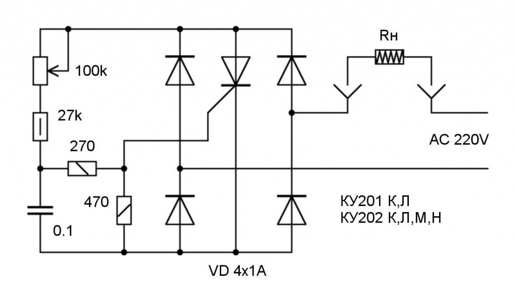
And here is a circuit in which two half-periods are regulated at once:
This is a dimmer, the voltage supplied from the network passes through the diode bridge and is rectified. The thyristor control circuit is powered by zener diodes. Thanks to the use of a bridge rectifier, it is possible to achieve the adjustment of both half-periods of the mains voltage.