In each aviation design bureau there is a bike about the statement of the chief designer. Only the author of the statement changes. And it sounds like this: "I have been engaged in airplanes all my life, but I still don’t understand how this piece of iron flies!" Indeed, the Newton’s first law has not yet been repealed, and the plane is clearly heavier than air. It should be understood what force does not allow the multi-ton machine to fall to the ground.
Air travel
There are three ways to travel:
- Aerostatic, when the separation from the earth is carried out using a body whose specific gravity is lower than the density of atmospheric air. These are balloons, airships, probes and other similar designs.
- Reactive, representing the brute force of a jet stream from combustible fuel, allowing to overcome the force of gravity.
- And finally, the aerodynamic method of creating lift when the Earth’s atmosphere is used as a supporting substance for vehicles heavier than air. Airplanes, helicopters, gyroplanes, gliders and, by the way, birds move using this particular method.
Aerodynamic forces
Four main multidirectional forces act on an airplane when moving through the air. Conventionally, the vectors of these forces are directed forward, backward, downward and upward. That is almost a swan, cancer and pike. The force pushing the aircraft forward is generated by the engine, backward is the natural force of air resistance, and downward is gravity. Well, it doesn’t allow the plane to fall - the lifting force generated by the air flow due to the flow around the wing.
Standard atmosphere
The state of air, its temperature and pressure can vary significantly in different parts of the earth's surface. Accordingly, all the characteristics of the aircraft will be different when flying in a particular place. Therefore, for convenience and bringing all characteristics and calculations to a common denominator, we agreed to determine the so-called standard atmosphere with the following basic parameters: pressure 760 mm Hg above sea level, air density 1.188 kg per cubic meter, sound speed 340.17 meters per second, temperature +15 ℃. With increasing altitude, these parameters change. There are special tables that reveal parameter values for different heights. All aerodynamic calculations, as well as the determination of the flight performance of aircraft are carried out using these indicators.
The simplest principle of creating lift
If you place a flat object in the oncoming air stream, for example, putting your hand palm out of the window of a moving car, you can feel this force, as they say, “on the fingers”. When you turn your palm a small angle relative to the air flow, it immediately feels that in addition to air resistance, there is another force pulling up or down, depending on the direction of the rotation angle. The angle between the plane of the body (in this case - the palm) and the direction of movement of the air flow is called the angle of attack. By controlling the angle of attack, you can also control the lifting force. You can easily notice that with an increase in the angle of attack, the force pushing the palm up will increase, but up to a certain point. And when you reach an angle close to 70-90 degrees, it will disappear altogether.
Airplane wing
The main bearing surface that creates lift is the wing of the aircraft. The wing profile, as a rule, has a curved droplet shape, as shown in the figure.
When a wing flows around an air stream, the speed of air passing along the upper part of the wing exceeds the speed of the lower stream. In this case, the static air pressure above becomes lower than under the wing. The pressure difference pushes the wing up, creating lift. Therefore, to ensure a pressure difference, all wing profiles are made asymmetric. For a wing with a symmetrical profile with a zero angle of attack, the lift in horizontal flight is zero. With such a wing, the only way to create it is to change the angle of attack. There is another component of the lifting force - inductive. It is formed due to the bevel of the air flow with the curved lower surface of the wing down, which naturally leads to the appearance of a reverse force directed upward and acting on the wing.
Payment
The formula for calculating the lift force of an airplane wing is as follows:
Y = Cy * S * (PV 2 ) / 2
Where:
- Cy is the lift coefficient.
- S - wing area.
- V is the speed of the oncoming flow.
- P is the density of air.
If everything is clear with the air density, wing area and speed, then the lift coefficient is a value obtained experimentally and is not a constant. It varies depending on the wing profile, its elongation, angle of attack, and other values. As you can see, the dependencies are mostly linear, with the exception of speed.
This mysterious coefficient
The wing lift coefficient is an ambiguous value. Complex multistage calculations are still verified experimentally. This is usually done in a wind tunnel. For each wing profile and for each angle of attack, its value will be different. And since the wing itself does not fly, but is part of an aircraft, such tests are carried out on the corresponding reduced copies of aircraft models. Less commonly, wings are tested separately. Based on the results of numerous measurements of each specific wing, it is possible to construct the dependences of the coefficient on the angle of attack, as well as various graphs that reflect the dependence of the lifting force on the speed and profile of a wing, as well as on the wing mechanization issued . A sample graph is shown below.
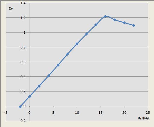
In fact, this coefficient characterizes the ability of the wing to convert the pressure of the incoming air into lifting force. Its usual value is from 0 to 2. The record is 6. So far, man is very far from natural perfection. For example, this coefficient for an eagle, when it rises from the ground with a gopher caught, reaches a value of 14. From the graph below it is obvious that an increase in the angle of attack causes an increase in lift to certain angle values. After which the effect is lost and even goes in the opposite direction.
Stall
As they say, everything is good in moderation. Each wing has its own limit in terms of angle of attack. The so-called supercritical angle of attack leads to disruption of the flow on the upper surface of the wing, depriving it of lift. Disruption occurs unevenly over the entire wing area and is accompanied by corresponding, extremely unpleasant phenomena such as jolting and loss of controllability. Oddly enough, this phenomenon does not depend much on speed, although it also affects, but the main reason for the occurrence of flow stall is intensive maneuvering, accompanied by supercritical angles of attack. It was because of this that the only crash of the IL-86 aircraft occurred, when the pilot, wanting to "show off" on an empty plane without passengers, abruptly began to gain altitude, which ended tragically.
Resistance
Hand in hand with lifting force is the drag force that impedes the forward movement of the aircraft. It consists of three elements. This is the friction force arising due to the effect of air on the aircraft, the force arising due to the pressure difference in the areas in front of the wing and behind the wing and the inductive component discussed above, since its action vector is not only directed upwards, contributing to an increase in the lifting force, but also backward, being an ally of resistance. In addition, one of the components of inductive resistance is the force arising from the flow of air through the ends of the wing, causing vortex flows that increase the bevel of the direction of air movement. The aerodynamic drag formula is absolutely identical to the lift formula, with the exception of the Su coefficient. It changes by the coefficient Cx and is also determined experimentally. Its value rarely exceeds one tenth of a unit.
Aerodynamic quality
The ratio of lift to drag is called aerodynamic quality. One thing to consider here. Since the formulas of the lifting force and the resistance force, with the exception of the coefficients, are the same, we can assume that the aerodynamic quality of the aircraft is determined by the ratio of the coefficients Su and Cx. The graph of this ratio for certain angles of attack is called the wing polar. A sample of this graph is shown below.
Modern airplanes have an aerodynamic quality value in the region of 17-21, and gliders - up to 50. This means that on airplanes the wing lifting force at optimal conditions is 17-21 times higher than the drag force. Compared to the Wright brothers' aircraft, with an estimate of 6.5, the progress in the design is obvious, but the eagle with the unfortunate ground squirrel in its claws is still far away.
Flight modes
Different flight modes require different aerodynamic quality. During cruising horizontal flight, the speed of the aircraft is quite high, and the coefficient of lift, proportional to the square of the speed, is at large values. The main thing here is to minimize resistance. During take-off and especially landing, the lift coefficient is crucial. The speed of the aircraft is low, but its stable position in the air is required. An ideal solution to this problem would be to create a so-called adaptive wing, changing its curvature and even area, depending on flight conditions, approximately the way birds do. Until the designers succeeded, a change in the coefficient of lift is achieved by the use of wing mechanization, which increases both the area and the curvature of the profile, which, by increasing resistance, significantly increases lift. For fighter aircraft, a change in wing sweep was applied. The innovation made it possible to reduce drag at high speeds and increase lift at low speeds. However, this design turned out to be unreliable, and recently, front-line aircraft are manufactured with a fixed wing. Another way to increase the lift force of an aircraft wing is to additionally blow the wing with the flow from the engines. This is implemented on military transport aircraft An-70 and A-400M, which due to this property are distinguished by shortened distances for takeoff and landing.