For a long and reliable cable service, it must be correctly selected and calculated. Electricians, when installing wiring, for the most part choose the cross section of the cores, based mainly on experience. Sometimes this leads to errors. The calculation of the cable cross-section is necessary, first of all, in terms of electrical safety. It will be wrong if the diameter of the conductor is less or more than required.
Cable cross section is underestimated
This case is the most dangerous, because the conductors overheat from a high current density, while the insulation melts and a short circuit occurs. In this case, electrical equipment can also be destroyed, a fire can occur, and workers can be energized. If you install a circuit breaker for the cable, it will trip too often, which will create some discomfort.
Cable section above required
Here the main factor is economic. The larger the cross-section of the wire, the more expensive it is. If you make the wiring of the entire apartment with a large margin, it will cost a large amount. Sometimes it is advisable to make the main input of a larger cross section, if a further increase in the load on the home network is expected.
If a suitable circuit breaker is installed for the cable, the following lines will be overloaded when one of them does not operate its circuit breaker.
How to calculate cable cross-section?
Before installation, it is advisable to calculate the cable cross section for the load. Each conductor has a certain power, which should not be less than that of connected electrical appliances.
Power calculation
The simplest way is to calculate the total load on the lead-in wire. Calculation of the cable cross-section by load is reduced to determining the total power of consumers. Each of them has its own denomination indicated on the case or in the passport. Then the total power is multiplied by a factor of 0.75. This is due to the fact that all devices cannot be turned on at the same time. For the final determination of the required size, the cable section calculation table is used.
Calculation of the cable cross section for current
A more accurate method is to calculate the current load. Calculation of the cable cross-section is made by determining the current passing through it. For a single-phase network, the formula is applied:
I calc. = P / (U nom ∙ cosφ),
where P is the load power, U nom. - network voltage (220 V).
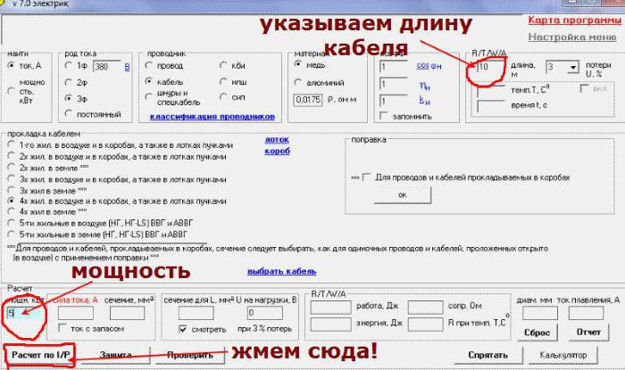
If the total power of the active loads in the house is 10 kW, then the rated current I calc. = 10000/220 ≈ 46 A. When calculating the cable cross-section by current, an adjustment is made for the conditions for laying the cord (indicated in some special tables), as well as for overload when electrical appliances are turned on approximately upwards by 5 A. As a result, I calc. = 46 + 5 = 51 A.
The thickness of the cores is determined by reference. Calculation of the cable cross-section using tables makes it easy to find the desired size by the long-term allowable current. For a three-core cable laid in the house through the air, you need to select a value in the direction of a larger standard section. It is 10 mm 2 . The correctness of the independent calculation can be checked by using the online calculator - the calculation of the cable section, which can be found on some resources.
Cable heating with current flow
When the load is operating, heat is generated in the cable:
Q = I 2 Rn W / cm,
where I is the current, R is the electrical resistance, n is the number of cores.
From the expression it follows that the amount of allocated power is proportional to the square of the current passed through the wire.
Calculation of permissible current strength according to the heating temperature of the conductor
The cable cannot heat up indefinitely, as heat dissipates into the environment. In the end, equilibrium sets in and a constant temperature of the conductors is established.
For a steady process, the ratio is true:
P = ∆t / ∑S = (t w - t cf. ) / (∑S),
where ∆t = t w -t cf is the difference between the temperature of the medium and the core, and ∑S is the temperature resistance.
The long-term allowable current passing through the cable is found from the expression:
I add = √ ((t add - t cf ) / (Rn∑S)),
where t add - permissible core heating temperature (depends on cable type and laying method). Usually it is 70 degrees in normal mode and 80 in emergency mode.
Heat dissipation conditions when the cable is running
When the cable is laid in any environment, the heat sink is determined by its composition and humidity. The estimated specific resistivity of the soil is usually taken equal to 120 Ohm ∙ ° C / W (clay with sand at a moisture content of 12-14%). To clarify, you should know the composition of the medium, after which you can find the resistance of the material in the tables. To increase thermal conductivity, the trench is covered with clay. The presence of building debris and stones in it is not allowed.
The heat transfer from the cable through the air is very low. It worsens even more when laying in the cable channel, where additional air gaps appear. Here, the current load should be reduced in comparison with the calculated one. In the technical characteristics of cables and wires, the permissible short circuit temperature is 120 ° C for PVC insulation. Ground resistance is 70% of the total and is the main in the calculations. Over time, the conductivity of the insulation increases due to its drying. This must be taken into account in the calculations.
Cable voltage drop
Due to the fact that the conductors have electrical resistance, part of the voltage goes to their heating, and less comes to the consumer than it was at the beginning of the line. As a result, potential is lost along the length of the wire due to heat loss.
The cable must not only be selected according to the cross-section to ensure its operability, but also take into account the distance over which energy is transmitted. An increase in load leads to an increase in current through the conductor. At the same time, losses increase.
Spotlights are lightly energized. If it decreases slightly, it is immediately noticeable. If the wires are improperly selected, the bulbs farther away from the power supply unit appear dull. The voltage is significantly reduced in each subsequent section, and this is reflected in the brightness of the lighting. Therefore, it is necessary to calculate the cable cross-section along the length.
The most important part of the cable is the consumer located further than the others. Losses are considered primarily for this load.
In the section L of the conductor, the voltage drop will be:
ΔU = (Pr + Qx) L / U n ,
where P and Q are active and reactive power, r and x - the active and reactive resistance of the plot L, and U n - rated voltage at which the load works normally.
Permissible ∆U from power sources to main inputs do not exceed ± 5% for lighting residential buildings and power circuits. From input to load, the loss should not be more than 4%. For lines with a large length, the inductive resistance of the cable must be taken into account, which depends on the distance between adjacent conductors.
Ways to connect consumers
Loads can be connected in different ways. The most common are the following methods:
- at the end of the network;
- consumers are evenly distributed across the line;
- a line with evenly distributed loads is connected to the extended section.
Example 1
The power of the appliance is 4 kW. The cable length is 20 m, the resistivity is ρ = 0.0175 Ohm ∙ mm 2 .
The current is determined from the ratio: I = P / U nom = 4 ∙ 1000/220 = 18.2 A.
Then, a table for calculating the cross section of the cable is taken, and the appropriate size is selected. For a copper wire, it will be S = 1.5 mm 2 .
The formula for calculating the cable section: S = 2ρl / R. Through it, you can determine the electrical resistance of the cable: R = 2 ∙ 0.0175 ∙ 20 / 1.5 = 0.46 Ohms.
Using the known value of R, it is possible to determine ΔU = IR / U ∙ 100% = 18.2 * 100 ∙ 0.46 / 220 ∙ 100 = 3.8%.
The calculation result does not exceed 5%, which means that losses will be acceptable. In case of large losses, it would be necessary to increase the cross-section of the cable conductors, choosing the adjacent, larger value from the standard series - 2.5 mm 2 .
Example 2
Three lighting circuits are connected in parallel with each other on one phase of a three-phase line, balanced on loads, consisting of a four-core cable of 70 mm 2 with a length of 50 m and a current carrying 150 A. A current of 20 A passes through each lighting line with a length of 20 m
Interfacial losses under the current load are: ∆U phases = 150 ∙ 0.05 ∙ 0.55 = 4.1 V. Now you should determine the losses between the neutral and the phase, since the lighting is connected to a voltage of 220 V: ∆U fn = 4 , 1 / √3 = 2.36 V.
On one connected lighting circuit, the voltage drop will be: ∆U = 18 ∙ 20 ∙ 0.02 = 7.2 V. The total losses are determined through the sum U total = (2.4 + 7.2) / 230 ∙ 100 = 4.2 % The calculated value is below the allowable loss, which is 6%.
Conclusion
To protect the conductors from overheating during a long-running load, tables are used to calculate the cable cross-section for a long-term permissible current. In addition, it is necessary to correctly calculate the wires and cables so that the voltage losses in them are not more than normal. At the same time, losses in the power circuit are summed with them.