Calculation of the heat exchanger currently takes no more than five minutes. Any organization that produces and sells such equipment, as a rule, provides everyone with its own selection program. It can be downloaded for free from the company's website, or their technical specialist will come to your office and install it for free. However, how correct is the result of such calculations, can it be trusted and will the manufacturer be cunning when fighting in the tender with its competitors? Testing an electronic calculator requires knowledge or at least an understanding of the calculation methods of modern heat exchangers. Let's try to figure out the details.
What is a heat exchanger
Before performing the calculation of the heat exchanger, let's remember what kind of device is this? A heat and mass transfer apparatus (aka heat exchanger, aka heat exchanger, or TOA) is a device for transferring heat from one heat transfer medium to another. In the process of changing the temperatures of the coolants, their density and, accordingly, the mass indicators of the substances also change. That is why such processes are called heat and mass transfer.
Heat Transfer Types
Now let's talk about the types of heat transfer - there are only three of them. Radiation - heat transfer due to radiation. As an example, you can recall sunbathing on the beach on a warm summer day. And such heat exchangers can even be found on the market (tube air heaters). However, most often for the heating of residential premises, rooms in an apartment we buy oil or electric radiators. This is an example of another type of heat transfer - convection. Convection can be natural, forced (exhaust hood, and there is a recuperator in the duct) or with mechanical motivation (with a fan, for example). The latter type is much more efficient.
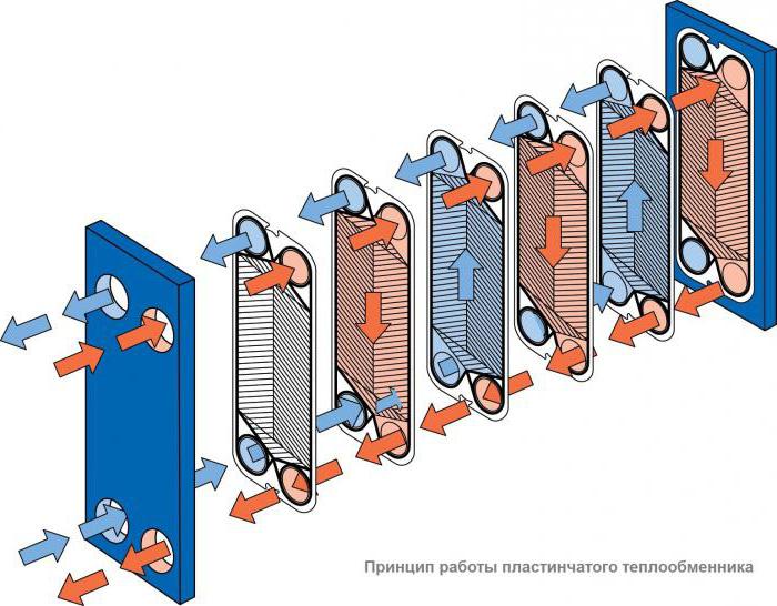
However, the most effective way of transferring heat is thermal conductivity, or, as it is also called, conduction (from the English conduction - "conductivity"). Any engineer who is going to conduct a heat calculation of a heat exchanger first of all thinks about choosing efficient equipment in the smallest dimensions. And this can be achieved precisely due to thermal conductivity. An example of this is the most effective TOA to date - plate heat exchangers. Plate TOA, by definition, is a heat exchanger that transfers heat from one coolant to another through a wall separating them. The maximum possible contact area between the two media in combination with correctly selected materials, the profile of the plates and their thickness allows you to minimize the size of the selected equipment while maintaining the original technical characteristics required in the process.
Types of heat exchangers
Before calculating the heat exchanger, it is determined with its type. All TOA can be divided into two large groups: recuperative and regenerative heat exchangers. The main difference between them is the following: in regenerative TOA, heat exchange occurs through the wall separating the two coolants, and in regenerative two media they have direct contact with each other, often mixing and requiring subsequent separation in special separators. Regenerative heat exchangers are divided into mixing and heat exchangers with a nozzle (stationary, falling or intermediate). Roughly speaking, a bucket of hot water exposed to frost, or a glass of hot tea, set to cool in the refrigerator (never do this!) - this is an example of such a mixing TOA. And when pouring tea in a saucer and cooling it in this way, we get an example of a regenerative heat exchanger with a nozzle (the saucer plays the role of a nozzle in this example), which first contacts the surrounding air and takes its temperature, and then takes part of the heat from the hot tea poured into it , seeking to bring both environments into thermal equilibrium. However, as we already found out earlier, it is more efficient to use thermal conductivity to transfer heat from one medium to another, therefore, TOA that are more useful in terms of heat transfer (and widely used) today are, of course, recuperative.
Thermal and structural analysis
Any calculation of a recuperative heat exchanger can be carried out on the basis of the results of thermal, hydraulic and strength calculations. They are fundamental, mandatory in the design of new equipment and form the basis of the methodology for calculating subsequent models of the line of devices of the same type. The main task of the thermal calculation of TOA is to determine the necessary area of the heat exchange surface for the stable operation of the heat exchanger and maintain the necessary parameters of the media at the outlet. Quite often, in such calculations, engineers are given arbitrary values of the mass and size characteristics of the future equipment (material, pipe diameter, plate sizes, beam geometry, type and material of fins, etc.), therefore, after a heat exchanger, a structural calculation of the heat exchanger is usually carried out. Indeed, if at the first stage the engineer calculated the necessary surface area for a given pipe diameter, for example, 60 mm, and the heat exchanger length was about sixty meters, it would be more logical to assume a transition to a multi-pass heat exchanger, or to a shell-and-tube type, or to increase the diameter of the tubes.
Hydraulic calculation
Hydraulic or hydromechanical, as well as aerodynamic calculations are carried out in order to determine and optimize the hydraulic (aerodynamic) pressure losses in the heat exchanger, as well as calculate the energy costs to overcome them. The calculation of any path, channel or pipe for the passage of the coolant poses a person the primary task - to intensify the heat transfer process in this area. That is, one medium must transfer, and the other receive as much heat as possible in the minimum interval of its flow. For this, an additional heat exchange surface is often used, in the form of developed surface finning (to detach the boundary laminar sublayer and enhance flow turbulization). The optimal balance ratio of hydraulic losses, heat exchange surface area, weight and size characteristics and heat output is the result of a combination of thermal, hydraulic and structural calculation of TOA.
Verification calculation
Calibration calculation of the heat exchanger is carried out in the case when it is necessary to lay the margin of power or the area of the heat exchange surface. The surface is reserved for various reasons and in different situations: if so required by the terms of reference, if the manufacturer decides to make an additional margin in order to be sure that such a heat exchanger will enter the mode and minimize errors made in the calculations. In some cases, redundancy is required to round off the results of structural dimensions, while in others (evaporators, economizers), a surface margin for contamination by compressor oil present in the refrigeration circuit is specially introduced in the calculation of the heat exchanger capacity . Yes, and poor water quality must be taken into account. After some time of trouble-free operation of the heat exchangers, especially at high temperatures, the scale deposits on the heat exchange surface of the apparatus, reducing the heat transfer coefficient and inevitably leading to a parasitic decrease in heat transfer. Therefore, a competent engineer, calculating the water-water heat exchanger, pays special attention to the additional reservation of the heat exchange surface. Verification calculation is also carried out in order to see how the selected equipment will work in other, secondary modes. For example, in central air conditioners (air handling units), heaters of the first and second heating, used in the cold season, are often used in the summer to cool the incoming air by supplying cold water to the tubes of the air heat exchanger. How they will function and which parameters will produce, allows you to evaluate the verification calculation.
Research calculations
TOA research calculations are carried out on the basis of the results of thermal and calibration calculations. They are necessary, as a rule, to make the latest amendments to the design of the designed device. They are also carried out in order to correct any equations laid down in the implemented TOA computational model obtained empirically (according to experimental data). Performing research calculations involves dozens, and sometimes hundreds, of calculations according to a special plan developed and implemented in production according to the mathematical theory of experimental design. The results reveal the influence of various conditions and physical quantities on the performance indicators of TOA.
Other calculations
When calculating the area of the heat exchanger, do not forget about the resistance of materials. Strength calculations of TOA include checking the designed unit for stress, torsion, for applying the maximum allowable working moments to parts and assemblies of the future heat exchanger. With a minimum size, the product must be strong, stable and guarantee safe operation in various, even the most demanding operating conditions.
Dynamic calculation is carried out in order to determine the various characteristics of the heat exchanger at variable modes of its operation.
Heat exchanger design types
Recuperative TOA by design can be divided into a fairly large number of groups. The most famous and widely used are plate heat exchangers, air (tubular finned), shell and tube, tube-in-tube heat exchangers, shell-plate heat exchangers and others. There are more exotic and highly specialized types, for example, spiral (snail heat exchanger) or scraper types that work with viscous or non-Newtonian fluids, as well as many other types.
Pipe-in-pipe heat exchangers
Consider the simplest design of a pipe-in-pipe heat exchanger. Structurally, this type of TOA is maximally simplified. As a rule, a hot coolant is allowed into the apparatus’s inner pipe to minimize losses, and a cooling coolant is launched into the casing or the outer pipe. The task of the engineer in this case is to determine the length of such a heat exchanger based on the calculated heat exchange surface area and the given diameters.
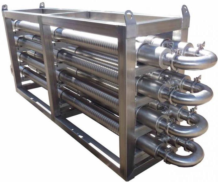
It is worth adding here that in thermodynamics the concept of an ideal heat exchanger is introduced, that is, an apparatus of infinite length, where the heat carriers work in countercurrent, and the temperature head is fully activated between them. The pipe-in-pipe construction closest to these requirements. And if you start the coolants in counterflow, then this will be the so-called “real counterflow” (and not cross, as in plate TOA). The temperature head is most effectively triggered by such an organization of movement. However, performing the calculation of the pipe-in-pipe heat exchanger, one should be realistic and not forget about the logistics component, as well as about the ease of installation. The length of the truck is 13.5 meters, and not all technical rooms are adapted for skidding and installation of equipment of this length.
Shell and tube heat exchangers
Therefore, very often the calculation of such an apparatus smoothly flows into the calculation of a shell-and-tube heat exchanger. This is an apparatus in which the tube bundle is located in a single casing (casing), washed by various coolants, depending on the purpose of the equipment. In condensers, for example, refrigerant is introduced into the casing and water into the tubes. With this method of moving media, it is more convenient and efficient to control the operation of the apparatus. In evaporators, on the contrary, the refrigerant boils in tubes, while they are washed by a cooled liquid (water, brines, glycols, etc.). Therefore, the calculation of the shell-and-tube heat exchanger is reduced to minimizing the dimensions of the equipment. While playing with the diameter of the casing, the diameter and number of internal pipes and the length of the apparatus, the engineer reaches the calculated value of the heat-exchange surface area.
Air heat exchangers
One of the most common heat exchangers to date is tubular finned heat exchangers. They are also called coils. Where they just can’t be installed, starting from fan coil units (from the English fan + coil, ie “fan” + “coil”) in the indoor units of split systems and ending with giant flue gas recuperators (heat extraction from hot flue gas and transmission it for heating) in boiler plants at the CHP. That is why the calculation of a coil heat exchanger depends on the application where this heat exchanger will go into operation. Industrial air coolers (VOPs), installed in shock freezing chambers of meat, in freezers of low temperatures and at other objects of food cold supply, require certain design features in their execution. The distance between the lamellas (fins) should be maximum, to increase the time of continuous operation between defrost cycles. Evaporators for data centers (data centers), on the contrary, are made as compact as possible, clamping interlamella distances to a minimum. Such heat exchangers operate in “clean zones” surrounded by fine filters (up to the HEPA class), therefore, such a calculation of a tubular heat exchanger is carried out with an emphasis on minimizing dimensions.
Plate Heat Exchangers
At present, plate heat exchangers are in stable demand. According to their design, they are completely collapsible and semi-welded, copper-soldered and nickel-brazed, welded and brazed by the diffusion method (without solder). The thermal calculation of the plate heat exchanger is quite flexible and does not represent much difficulty for the engineer. In the selection process, you can play with the type of plates, the depth of stamping of the channels, the type of fins, the thickness of the steel, various materials, and most importantly, the numerous standard-sized models of devices of different sizes. Such heat exchangers are low and wide (for steam heating of water) or high and narrow (separation heat exchangers for air conditioning systems). They are often used also under phase transition media, that is, as condensers, evaporators, desuperheaters, pre-condensers, etc. It is a little more difficult to perform a thermal calculation of a heat exchanger operating in a two-phase circuit than a liquid-liquid heat exchanger, however, for an experienced engineer, this problem is solvable and not particularly difficult. To facilitate such calculations, modern designers use engineering computer bases where you can find a lot of necessary information, including status diagrams of any refrigerant in any scan, for example, the CoolPack program.
Heat exchanger calculation example
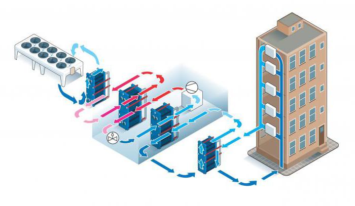
The main purpose of the calculation is to calculate the required heat exchange surface area. Thermal (refrigerating) power is usually set in the terms of reference, however, in our example, we will calculate it, for, let's say, check the terms of reference. Sometimes it also happens that an error may sneak into the source data. One of the tasks of a competent engineer is to find and fix this error. As an example, we perform the calculation of a plate heat exchanger of the "liquid - liquid" type. Let it be a pressure breaker in a tall building. In order to relieve pressure equipment, this approach is often used in the construction of skyscrapers. On one side of the heat exchanger we have water with an inlet temperature of Twx1 = 14 ᵒC and an outlet of Twx1 = 9 ᵒC, and with a flow rate of G1 = 14 500 kg / h, and on the other - also water, but only with the following parameters: Twx2 = 8 ᵒC, Thy2 = 12 ° C, G2 = 18 125 kg / h.
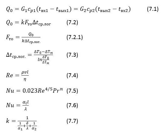
The required power (Q0) is calculated using the heat balance formula (see. Fig. Above, formula 7.1), where is the specific heat (tabular value). For simplicity of calculations, we take the reduced value of specific heat = 4,187 [kJ / kg * ᵒ]. We consider:
Q1 = 14 500 * (14 - 9) * 4.187 = 303557.5 [kJ / h] = 84321.53 W = 84.3 kW - on the first side and
Q2 = 18 125 * (12 - 8) * 4,187 = 303557,5 [/] = 84321,53 = 84,3 – .
, , (7.1), Q0 = Q1 = Q2, , .
(7.2) (7.2.1), k – ( 6350 [/ 2 ]), Δ.. – , (7.3):
Δ .. = (2 - 1) / ln (2 / 1) = 1 / ln2 = 1 / 0,6931 = 1,4428;
F = 84321 / 6350 * 1,4428 = 9,2 2 .
, . (7.4) , ρ – , [/ 3 ], η – , [*/ 2 ], v – , [/], d – [].
[Pr] (7.5) , n = 0,4 – , n = 0,3 – .
Further, by the formula (7.6), the heat transfer coefficient from each heat carrier to the wall is calculated, and by the formula (7.7) we calculate the heat transfer coefficient, which we substitute in the formula (7.2.1) to calculate the area of the heat exchange surface.
In the indicated formulas, λ is the thermal conductivity coefficient, ϭ is the channel wall thickness, α1 and α2 are the heat transfer coefficients from each of the coolant walls.