The first of all rotating electric machines invented in the 19th century is a DC motor. The principle of its operation has been known since the middle of the last century, and to this day, DC motors (DC) continue to faithfully serve a person, setting in motion many useful machines and mechanisms.
The first DPT
Since the 30s of the 19th century, they have gone through several stages in their development. The fact is that until the advent of machine alternators at the end of the last century , the only source of electricity was a galvanic cell. Therefore, all the first electric motors could only work on direct current.
What was the first DC motor? The principle of operation and arrangement of engines built in the first half of the 19th century was as follows. The explicit pole inductor was a set of fixed permanent magnets or rod electromagnets that did not have a common closed magnetic circuit. The explicit pole anchor was formed by several separate rod electromagnets on a common axis, driven into rotation by the forces of repulsion and attraction to the poles of the inductor. Their typical representatives were the engines of W. Ricci (1833) and B. Jacobi (1834), equipped with mechanical current commutators in electromagnets of the armature with movable contacts in the armature winding circuit.
How the Jacobi engine worked
What was the operating principle of this machine? The Jacobi DC motor and its analogues had a pulsating electromagnetic moment. During the time of approaching the opposite poles of the armature and inductor under the influence of magnetic force of attraction, the motor moment quickly reached a maximum. Then, when the poles of the armature were opposite the poles of the inductor, the mechanical switch interrupted the current in the electromagnets of the armature. The moment fell to zero. Due to the inertia of the armature and the mechanism driven by the mechanism, the armature poles came out from under the poles of the inductor, at this moment a current of the opposite direction was supplied to them from the switch, their polarity also changed to the opposite, and the attractive force to the nearest pole of the inductor was replaced by the repulsive force. Thus, the Jacobi engine rotated in successive thrusts.
A ring anchor appears
In the rod electromagnets of the Jacobi motor armature, the current was periodically turned off, the magnetic field created by them disappeared, and its energy was converted into heat losses in the windings. Thus, the electromechanical conversion of electricity from the current source of the armature (galvanic cell) into mechanical occurred in it intermittently. What was needed was an engine with a continuous closed winding, the current in which would flow continuously throughout the entire time of its operation.
And such a fuhtufn was created in 1860 by A. Pacinotti. How did his DC motor differ from its predecessors? The principle of operation and design of the Pacinotti engine are as follows. As an anchor, he used a steel ring with knitting needles mounted on a vertical shaft. In this case, the anchor did not have pronounced poles. He became implicit.
Between the spokes of the ring, coils of the armature winding were wound, the ends of which were connected in series on the anchor itself, and from the points of connection of each two coils, solders were made attached to the collector plates located along a circle below the motor shaft, the number of which was equal to the number of coils. The entire armature winding was closed on itself, and the successive connection points of its coils were connected to neighboring collector plates, along which a pair of current-carrying rollers slid.
An annular anchor was placed between the poles of two stationary electromagnets of the inductor-stator, so that the lines of force of the excitation magnetic field created by them entered the outer cylindrical surface of the motor armature under the north excitation pole, passed through the annular armature without moving into its inner hole, and went outside under the south pole.
How did the Pacinotti engine work
What was his principle of action? Pacinotti's DC motor worked just like modern DCTs.
In the magnetic field of the pole of the inductor with a given polarity, there was always a certain number of conductors of the armature winding with the current in the same direction, and the direction of the armature current under the opposite poles of the inductor was opposite. This was achieved by placing current-carrying rollers playing the role of brushes in the space between the poles of the inductor. Therefore, the instantaneous armature current flowed into the winding through the roller, the collector plate and the tap attached to it, which was also in the space between the poles, then flowed in opposite directions along the two half-winding branches, and finally flowed through the tap, the collector plate and the roller in another pole the gap. In this case, the armature coils themselves under the poles of the inductor changed, but the direction of the current in them remained unchanged.
According to Ampere’s law , a force acted on each conductor of the armature coil of the armature with a current in the magnetic field of the pole of the inductor, the direction of which is determined by the well-known rule of the “left hand”. Relative to the axis of the engine, this force created a torque, and the sum of the moments from all such forces gives the total moment of the DPT, which is already almost constant with several collector plates.
DPT with ring anchor and gram winding
As it often happened in the history of science and technology, the invention of A. Pacinotti did not find application. It was forgotten for 10 years, until in 1870 it was independently repeated by the Franco-German inventor Z. Gram in a similar design of a DC generator. In these machines, the axis of rotation was already horizontal, carbon brushes were used, sliding on the collector plates of an almost modern design. By the 70s of the 19th century, the principle of reversibility of electric machines was already well known, and the Gram machine was used as a generator and a DC motor. The principle of its operation has already been described above.
Despite the fact that the invention of the ring anchor was an important step in the development of DPT, its winding (called Gram's) had a significant drawback. In the magnetic field of the poles of the inductor were only those of its conductors (called active), which lay under these poles on the outer cylindrical surface of the armature. It was to them that Ampere’s magnetic forces were applied , creating a torque relative to the axis of the engine. The same inactive conductors that passed through the hole of the annular anchor did not participate in the creation of the moment. They only uselessly dissipated electricity in the form of heat loss.
From the ring anchor to the drum
In 1873, the famous German electrical engineer F. Gefner-Altenek managed to eliminate this drawback of the ring anchor. How did his DC motor function? The principle of operation, the device of its inductor-stator are the same as that of an engine with a ring winding. But the design of the anchor and its winding have changed.
Gefner-Altenek noted that the direction of the armature current flowing from the fixed brushes in the conductors of the gram winding under adjacent excitation poles is always the opposite, i.e. they can be included in the composition of the coils located on the outer cylindrical surface of the coil with a width (pitch) equal to the pole division (the part of the armature circle per one excitation pole).
In this case, the hole in the annular anchor becomes unnecessary, and it turns into a solid cylinder (drum). Such a winding and the anchor itself were called drum. The copper consumption in it with the same number of active conductors is much less than in the gram winding.
Anchor becomes jagged
In Gramm and Gefner-Altenek machines, the surface of the armature was smooth, and the conductors of its winding were located in the gap between it and the poles of the inductor. In this case, the distance between the concave cylindrical surface of the excitation pole and the convex surface of the armature reached several millimeters. Therefore, to create the desired magnitude of the magnetic field, it was required to use excitation coils with a large magnetomotive force (with a large number of turns). This significantly increased the size and weight of the engines. In addition, it was difficult to mount on the smooth surface of the anchor of his coil. But what to do? Indeed, to act on a conductor with a current of Ampere force, it must be at points in space with a large magnetic field (with large magnetic induction).
It turned out that this is not necessary. The American inventor of the machine gun, H. Maxim, showed that if the drum anchor is serrated, and the coils of the drum winding are placed in the grooves formed between the teeth, the gap between it and the excitation poles can be reduced to fractions of a millimeter. This made it possible to significantly reduce the size of the excitation coils, but the torque of the DPT did not decrease at all.
How does such a DC motor function? The principle of operation is based on the fact that with a toothed anchor, magnetic force is applied not to the conductors in its grooves (there is practically no magnetic field in them), but to the teeth themselves. Moreover, the presence of current in the conductor in the groove is crucial for the occurrence of this force.
How to get rid of eddy currents
Another major improvement was made by the famous inventor T. Edisson. What did he add to the DC motor? The principle of action has remained unchanged, but the material from which its anchor is made has changed. Instead of the former massive, it became burdened from thin steel sheets electrically isolated from each other. This made it possible to reduce the magnitude of eddy currents (Foucault currents) in the armature, which increased the efficiency of the motor.
The principle of operation of a DC motor
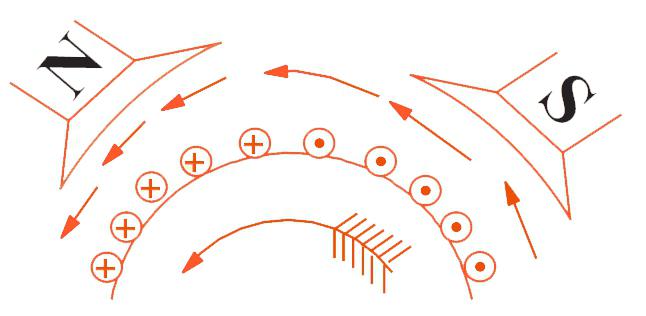
Briefly, it can be formulated as follows: when a winding of the armature of an excited motor is connected to a power source, a large current arises in it, called a starting current and several times higher than its rated value. Moreover, under the poles of excitation of opposite polarity, the direction of the currents in the conductors of the armature winding is as opposite, as shown in the figure below. According to the “left hand” rule, these conductors are affected by Ampere forces directed counterclockwise and dragging the anchor into rotation. In this case, an electromotive force (counter-EMF) is directed in the conductors of the armature winding directed counter to the voltage of the power source. As the armature accelerates, the counter-EMF in its winding also grows. Accordingly, the armature current decreases from the starting to the value corresponding to the operating point on the motor characteristic.
To increase the speed of rotation of the armature, you must either increase the current in its winding, or reduce the counter-EMF in it. The latter can be achieved by reducing the magnitude of the magnetic field of the excitation by reducing the current in the excitation winding. This method of controlling the speed of DPT is widespread.
The principle of operation of a DC motor with independent excitation
With the connection of the field winding (OV) terminals to a separate power supply (independent OV), powerful DCTs are usually made to make it more convenient to control the magnitude of the excitation current (in order to change the rotation speed). According to their properties, DCTs with independent RH are almost similar to DCTs with OV, connected in parallel to the armature winding.
Parallel excitation of DPT
The principle of operation of a DC motor of parallel excitation is determined by its mechanical characteristic, i.e. the dependence of the rotation speed on the load moment on its shaft. For such an engine, the change in speed during the transition from idle to the rated load moment is from 2 to 10%. Such mechanical characteristics are called rigid.
Thus, the principle of operation of a DC motor with parallel excitation determines its use in drives with a constant speed of rotation with a wide range of load changes. However, it is widely used in a variable speed variable speed drive. In this case, to control its speed, a change in both the armature current and the excitation current can be applied.
Sequential DPT Excitation
The principle of operation of a DC motor of serial excitation, as well as parallel, is determined by its mechanical characteristic, which in this case is soft, because engine speed varies significantly with load changes. Where is it best to use such a DC motor? The principle of operation of the railway traction motor, the speed of which should decrease when overcoming the composition of the rises and return to the nominal value when moving along the plain, fully complies with the characteristics of the DCT with OB connected in series with the armature winding. Therefore, a significant part of electric locomotives around the world is equipped with such devices.
The principle of operation of a DC motor with series excitation is also realized by pulsating current traction motors, which are, in fact, the same DC motors with a series of alternating current, but specially designed to work with a current rectified on board an electric locomotive, which has significant ripple.