An induction motor is an alternating current electric motor . This electric machine is called asynchronous because the frequency with which the moving part of the motor rotates - the rotor, does not equal the frequency with which the magnetic field rotates, which is created due to the flow of alternating current through the winding of the immovable part of the motor - stator. Asynchronous motor - the most common of all electric motors, it has received widespread popularity in all industries, engineering and more.
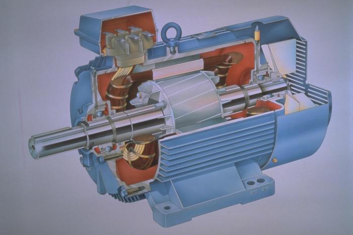
The induction motor in its design necessarily has two most important parts: the rotor and the stator. These parts are separated by a small air gap. Active parts of the engine can also be called windings and magnetic circuit. Structural parts provide cooling, rotor rotation, strength and rigidity.
The stator is a cast steel or cast iron housing of a cylindrical shape. Inside the stator housing there is a magnetic circuit, in the special cut-out grooves of which the stator winding is laid. Both ends of the winding are displayed in the terminal box and are connected either by a triangle or by a star. At the ends, the stator housing is completely covered by bearings. The bearings on the rotor shaft are pressed into these bearings. The rotor of an induction motor is a steel shaft, on which a magnetic circuit is also pressed.
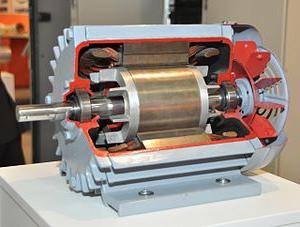
Structurally, the rotors can be divided into two main groups. The engine itself will bear its name in accordance with the principle of design of the rotor. The squirrel cage induction motor is the first type. There is a second one. This is an asynchronous motor with a phase rotor. Aluminum grooves are poured into the grooves of the engine with the squirrel-cage rotor (it is also called the “squirrel cage” due to the similarity of the appearance of such a rotor to the cage of a squirrel) and close them at the ends. The phase rotor has three windings that are connected to each other in a star. The ends of the windings are attached to rings fixed to the shaft. When the engine starts, special fixed brushes are pressed to the rings. Resistors are connected to these brushes to reduce the starting current and smoothly start the induction motor. In all cases, a three-phase voltage is applied to the stator winding.
The principle of operation of any induction motor is simple. It is based on the famous law of electromagnetic induction. The stator magnetic field created by the three-phase voltage system rotates under the action of the current passing through the stator winding. This magnetic field crosses the winding and conductors of the rotor winding. From this, an electromotive force (EMF) is created in the rotor winding according to the law of electromagnetic induction. This EMF causes leakage in the winding of the AC rotor. This rotor current subsequently creates a magnetic field itself, which interacts with the magnetic field of the stator. This process also starts the rotation of the rotor in magnetic fields.
Often, to reduce the starting current (and it can be many times higher than the operating current for an induction motor), starting capacitors are used , connected in series to the starting winding. After start-up, this capacitor turns off, keeping the performance unchanged.