In the Soviet Union, various model sections, usually existing at the pioneer palaces, were very widespread. The main activity of the young modellers was the independent production of models of aircraft and ships with various types of engines.
General information
The simplest models were equipped with the so-called rubber engine, which was a twisted bundle of rubber strips. One side of the tourniquet was fixed on the model's case, and a propeller or propeller was attached to the second. Older modellers built models and models equipped with several types of engines:
- electrically powered;
- piston compression type;
- piston-fired ignition mixture.
Compression engines have a simple design and do not require separate starting devices. That is why they are most prevalent. Ignition of the mixture is carried out from compression, while the volume of the chamber is regulated by a special device.
Motor design
The MK-17 engine was created by V. Petukhov, a well-known aircraft modeller and master of sports in this discipline. The date of development of the motor is not exactly known, but by 1954 the first samples already existed. The designer set himself the goal of creating a reliable engine that could be used by novice modelers, reliable in starting and operating.
The design of the motor was very simple, which predetermined its prevalence. Serial production of the MK-17 Junior engine was carried out at the Znamya Revolyutsii factory (Moscow). Structurally, the motor consists of the following main parts:
- Cast silumin sump.
- Replaceable cast iron sleeve.
- Crankshaft.
- Smooth piston with connecting rod and finger.
- Spool valve and interchangeable diffuser.
- A cylinder head having several ribs.
- Counter piston and screw for moving it.
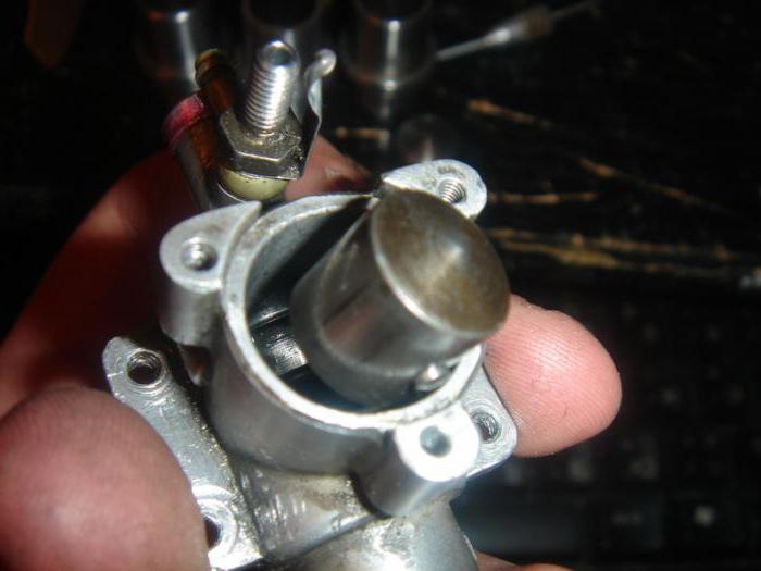
Next, a general description of the MK-17 aircraft model engine will be given, which is typical for all model compression-type engines. The motor shaft rotates on a pair of ball bearings, which are pressed into the lower part of the crankcase. On the shaft there is a counterweight and a neck with one free end. A connecting rod is put on this neck and a spool valve, which serves to supply fuel, is driven. A finger is installed on the top of the connecting rod connecting it with the cast-iron piston. The upper part of the piston has the shape of a cone, while the counter-piston has a reciprocal recess. A diffuser and a primitive carburetor are installed on the rear of the engine, which allows you to adjust the amount of fuel supplied with a needle. The diffuser was produced in two sizes - small and large. The first option was used by novice modelers, and the second was already more experienced. The spool assembly is mounted through a cardboard gasket on four screws.
An aluminum head with six thick ribs was installed on the upper part of the crankcase. The head was attracted by three screws and fixed the replaceable sleeve. There were windows in the walls of the liner through which a fresh mixture was supplied and exhaust was released. The exhaust windows were located under the plane of attachment of the head. The working volume of the cylinder was only 1.48 cubic meters. cm.
Thanks to all the improvements, the power increased, which reached 165 watts, and the maximum engine speed (up to 12 thousand per minute when working with a propeller). The weight of the motor was about 130 grams.
Fuel
The MK-17 engine could use only a special mixture as fuel. Its composition necessarily included sulfur dioxide, which has high volatility and low flash point. It was this component that ensured the self-ignition of the mixture. In addition, fuel included kerosene and castor oil, which provided lubrication for all rubbing elements. The proportional ratio of the components is almost equal (35% of kerosene and ether, and the rest is castor oil).
Currently, to start the MK-17 engines, a carburetor cleaner is used instead of ether.
Launch
To start the engine, it is necessary to fill the fuel in the tank, loosen the counter-piston fixing screw a few turns and turn the shaft by hand. In doing so, use your finger to pinch the diffuser hole. A certain amount of fuel will get inside the engine. Then it is necessary to sharply turn the motor shaft by the screw. If there are no flashes or they are single, then it is necessary to increase the compression ratio by tightening the screw in the head. Then rotate the shaft again and try to start the engine.
After starting, you need to set the required speed with the needle and vary the position of the screw in the head, achieving the most stable operation. The motor is stopped by closing the diffuser or closing the needle.
Modifications and alterations
By finalizing the motors, it was meant to verify the actual gas distribution diagrams with the passport documentation. At the same time, purge windows were trimmed in the liner or a new liner was replaced in case of too high a window height.
One of the most common alterations of the motor is the installation of a glow plug in place of the counter-piston screw. The counter-piston itself was removed from the cylinder. Such a conversion turned the MK-17 compression engine into a glow engine.