The trigger is an elementary digital machine. It has two states of stability. One of them is assigned the value “1”, and the other - “0”.
By the method of implementing logical connections, the following types of devices are distinguished: JK-trigger, RS-trigger, T-trigger, D-trigger , etc.
The subject of our conversation today is JK. They differ from RS devices in that when information forbidden for RS triggers is input, they invert the information stored in them.
We present to your attention a transition table that describes the operation of the JK trigger. When minimizing the Carnot kata, the characteristic equation for the device in question is derived: Q (t + 1) = K't Qt V Jt Q't.
It can be seen from the table that the state of the device is determined not only by the information values at the inputs J and K, but also by the state at the output Qt, which previously determined the JK trigger. This allows you to build functional diagrams of such devices on two-stage automatic machines of the RS type. JK devices are synchronous and asynchronous.
To design a JK trigger from a two-stage RS device of a synchronous type, it is necessary to connect the feedbacks of the outputs of the two-stage RS automaton with the inputs of the logic elements of its first stage.
The principle of operation of the JK trigger: if a zero level is applied to the information (J and K) inputs of the device, then the unit level is set at the output of the AND-NOT elements (1 and 2), and the JK trigger retains its state. For example, Q will be a logical zero, Q '- a logical unit. In this case, when signals J and C are equal to a logical unit, a logical zero and, correspondingly, the level of a logical unit at the input of the first T-trigger are set at the input of the AND-NOT1 element. When the synchronization signal is removed (C is equal to zero), the state of the aforementioned T-type device by the level of logical zero from the output AND = NOT3 will be transmitted to the input of the second T-trigger. As a result, the JK trigger will switch to the state of the logical unit (in this case, Q is equal to one, and Q 'is equal to zero). Now, if a signal equal to a logical one is supplied at the input of the trigger (K and C), then at the output of the I-HE2 element a logical zero will set the first T-trigger to zero. After removing the synchronizing signal from the output of the I-HE4 element, a logic zero is transmitted to the input of a second T-type automaton, and the JK trigger switches to the logical zero state.
When designing complex logic circuits, devices of different types are needed. Therefore, it is more profitable to make a universal type of device that can be used in various operating modes and modifications. In integrated circuitry, synchronous D- and JK-triggers are most widely used. In electronic computers, JK type digital machines are widely used with group J, K and additional installation R, S inputs. Each group is united by a conjunction, which allows you to expand the logical capabilities and JK-trigger.
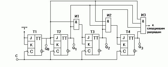
Automated devices of this type are conveniently used in the design of counters (a computer unit that counts and stores the code for the number of counted signals). For example, the photo shows a counter on JK triggers. The structural organization of binary counters with parallel transfer is greatly simplified if they are built on devices like JK with built-in logic elements I.
Also, such triggers have found application in the design of shifting registers.
Shift registers are nodes that shift binary information to the right and left in the register, depending on the control signals.