This article will examine in detail the circuit of a vacuum tube amplifier . Of course, this technique has long been outdated, but to this day you can meet fans of the "retro". Someone simply prefers tube sound to digital, and someone is committed to giving a second life to equipment that has become unusable, restoring it bit by bit. Many radio amateurs who work on the air use lamps to build some cascades of circuits. For example, UHF is easier to build on high-power lamps, since on transistors they will be too complicated.
Amplifier block diagram
The block diagram is as follows:
- Signal source (microphone, telephone, computer output, etc.).
- Volume control - potentiometer (variable resistor).
- A preamplifier built on a lamp (usually a triode), or on a transistor.
- The tone control circuit is connected to the anode circuit of the pre-amp lamp.
- Terminal amplifier. Usually performed on a pentode, for example, 6P14S.
- A matching device that allows you to dock the output of the amplifier and the speaker system. As a rule, this role is played by a step-down transformer (220/12 Volts).
- A power supply unit in which two voltages are generated: a constant 250-300 V and an alternating 6.3 V (12.6 V if necessary).
According to the structural scheme, the principal is built. It is necessary to thoroughly examine each node of the system so that the manufacture of the amplifier does not cause problems.
Power amplifier bass
As mentioned above, the power supply must generate two different voltages by value. For this you need to use a special design transformer. It should have three windings - network, secondary and tertiary. The last two generate alternating voltage of 250-300 V and 6.3 V, respectively. 6.3 V is the voltage of the filament of the radio tubes. And if it, as a rule, does not need any processing, for example, filtration and rectification, then the alternating 250 Volts needs to be changed a little. This requires the connection of the amplifier to the power source.
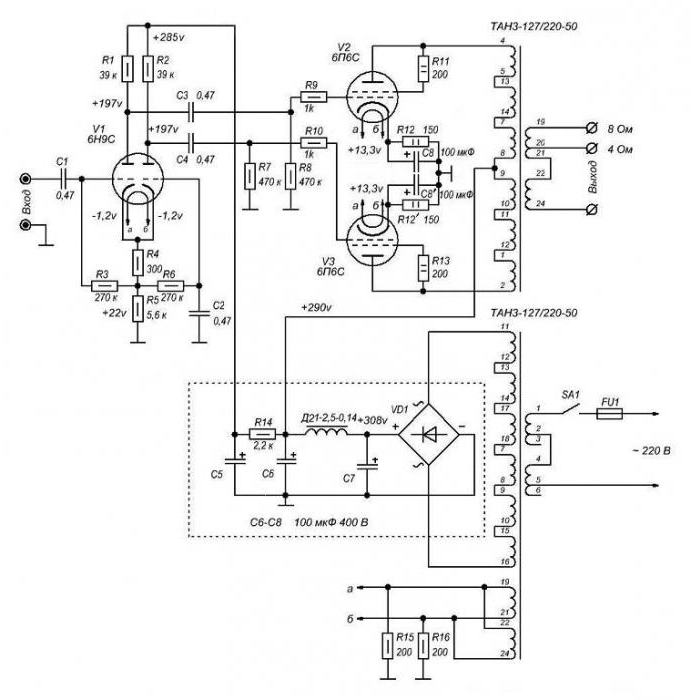
For this, a rectifier block is used, which consists of four semiconductor diodes, and filters are electrolytic capacitors. Diodes allow you to rectify the alternating current and make it constant. And capacitors have an interesting feature. If you look at the equivalent circuit of capacitors for alternating and direct current (according to the law of Kirchhoff), you can see one feature. When working in DC circuits, the capacitor is replaced by a resistance.
But when working in an alternating current circuit, it is replaced by a piece of conductor. In other words, when installing capacitors in the power supply unit, you will get a pure constant voltage, the entire variable component will disappear due to the short-circuited conclusions in the equivalent circuit.
Transformer Requirements
An important condition is the availability of the required number of windings to power the anodes and filaments of the lamps. Depending on which power amplifier circuit is used , a different voltage supply voltage is required. The standard value is 6.3 V. But some lamps, for example G-807, GU-50, need a voltage of 12.6 V. This complicates the design and forces the use of a large transformer.
But if you plan to assemble the amplifier exclusively on finger lamps (6H2P, 6P14P, etc.), then there is no need for such a voltage supply voltage. Pay attention to the dimensions - if you need to assemble a small amplifier, then use single-coil transformers. They have one drawback - it is impossible to get high power. If there is a question in power, then it is better to use transformers of the TS-180, TS-270 type.
Case for device
For low-frequency amplifiers, it is best to use an aluminum or galvanized enclosure; the installation of radio elements is done by a hinged method. The drawback of assembling the device on a printed circuit board is that due to heating, the legs of the sockets for the lamps begin to peel off from the tracks, the soldering is destroyed. Contact disappears, and the ULF operation becomes unstable, extraneous sounds appear.
If in the preliminary cascade the transistor amplifier circuit is used, then it is more reasonable to make it on a small piece of PCB - it will be more reliable. But the use of a hybrid scheme has its own nutritional requirements. For the guitar, the ULF can be arranged in a wooden case. But inside you need to install a metal chassis on which the entire device will be assembled. It is advisable to use a metal case, since it allows you to easily shield the cascades from each other, which eliminates the possibility of self-excitation and other interference.
Volume and Tone Control
The circuit of a simple amplifier can be supplemented by two adjustments - volume and timbre. The first regulator is installed directly at the input of the ULF, allows you to change the value of the incoming signal. You can use variable resistors of any design that will work fine in the ULF. There should be no problems with tone control either - a variable resistor is included in the anode circuit of the first stage. It is only necessary to determine in which direction the rotation is performed in order to add the treble, and in which to build the bass.
It is advisable to do everything like industrial amplifiers, otherwise it will be inconvenient to use the design. But this is the simplest tone control scheme, it is more reasonable to install a small block that will allow you to change frequencies in a wide range. Circuits of tube amplifiers may contain small modules on semiconductors - timbral blocks, low-pass filters. If there is no desire to make a timbral block yourself, then it can be purchased in stores. The cost of such timbroblocks is quite low.
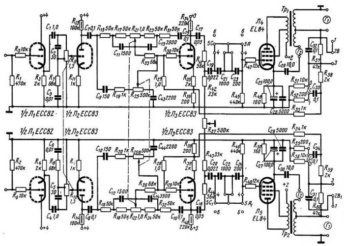
Stereo amplifier
But stereo LF is much more pleasant to listen to than monophonic. And to make it twice as difficult - you need to assemble another ULF with the same parameters. As a result, you get two inputs and the same number of outputs. Moreover, the circuit of the power amplifier and preliminary stages must be identical, otherwise the characteristics will vary.
All capacitors and resistors are the same in parameters - in terms of values and tolerances. A special requirement for variable resistances is that it is necessary to use paired structures for both volume controls and the timbral block. The point is that it is necessary to ensure uniform adjustment of these parameters in both channels.
System 2.1
But to improve the sound quality, you can add a subwoofer that will amplify low frequencies. In this case, the general connection diagram of the amplifier will not change, only the third block will be added. In fact, you should get three completely identical monophonic amplifiers - one per left channel, right, subwoofer.
Please note that the volume control in the subwoofer is separate from the ULF. This will allow you to further change the gain level. Cutoff of the "extra" frequencies is carried out using a simple circuit, which includes several capacitors and resistances. But you can use ready-made low-pass filters, which are sold in any store of radio components.
Conclusion
Above were considered schemes of tube amplifiers, which are most often repeated by ham radio in their designs. Independently make them under the force of a person who knows how to handle a soldering iron and technical literature. But if you do not distinguish a resistor from a capacitor and do not seek to learn anything, but you need an amplifier, then it is better to ask an experienced master to make a ULF.